Could someone please explain how to use the VCCS
I can understand why the voltage regulation is important
Is there a benefit from current regulation too
Are the LDR sensitive to current inrush, etc
How many LDR lightspeed unit can be used with one VCCS
Cant seem to find specs on Paul Hynes site
I can understand why the voltage regulation is important
Is there a benefit from current regulation too
Are the LDR sensitive to current inrush, etc
How many LDR lightspeed unit can be used with one VCCS
Cant seem to find specs on Paul Hynes site
Lightspeed remote control
Hi Folks,
Here are the circuit diagrams for the revised remote control system :
the VCCS

The IR transmitter

The IR receiver

and the board layouts for
the VCCS lightspeed MKII application

the IR transmitter and receiver

Most of you should be able to sort out your application from this information. Any questions, post them on the forum thread.
The resistors R1-R4 in the VCCS module control the working range of the LDRs. I have used 39k values to approximate the range suggested by Nelson Pass when he posted some test results of his experiments a while back. These values work fine in my system but you may need to alter the resistance values to match your system voltage gain and efficiency criteria.
Hi Alan,
This is the best I can do for you this week as I have a rather large workload to plough through. The wall to wall sunshine I have missed for the last three days has not helped. When I catch up and get some free time it will be wet and windy.
Hope this helps. If you need further info, ask and I will answer as soon as I get chance.
It is quite time consuming going through the catalogues. I'm really pleased you took this job on, Alan.
Regards
Paul
Lightspeed remote control
Hi Tinitis,
The VCCS module has a push button interface utilising the DS1802 volume control chip to drive complementary voltage controlled current sources which in turn drive the light emmitting diodes in the LDR component. I chose this system because it was easy to set up remote control for my own requirements. If you have no need of remote control you can use push buttons to directly control the VCCS. The remote control receiver can be used in parallel with the push buttons on the preamp chassis.
As far as the prefered method of LDR control is concerned I have not done direct comparisons and as the remote control does what I want and the LDRs are so transparent I am happy to not bother comparing. There are some comments about sonic improvements driving the LDRs from current sources in past posts on the forum thread if you care to read through it.
How many lightspeeds do you want to control with the VCCS? Talk about your application requirement and we might be able to help.
I have not posted anything on my website about the Lightspeed remote control.
Regards
Paul
BOM
I have completed the BOM and loaded the Mouser version - I will check it out tomorrow and load it for someone to check.
By then some people will havebeen able to go through Paul's diagrams and photos of the boards.
Alan
I have completed the BOM and loaded the Mouser version - I will check it out tomorrow and load it for someone to check.
By then some people will havebeen able to go through Paul's diagrams and photos of the boards.
Alan
Re: Lightspeed remote control
I had this in mind
Fore ease of indidual setting on poweramps, and versatility
Maybe even with mono pots, if possible
Though just remembered that George recommends to adjust LDR volume down below half setting, which supposedly would result in less wear on LDR
Not sure if its an issue to take very serious
But the LDR on my outputs would probably always be set on the high, which means the last half
Could that be wearing them down early 🙄
Or will I be facing other LDR related problems as well
maximus said:Hi Tinitis,
How many lightspeeds do you want to control with the VCCS? Talk about your application requirement and we might be able to help.
Paul
I had this in mind
Fore ease of indidual setting on poweramps, and versatility
Maybe even with mono pots, if possible
Though just remembered that George recommends to adjust LDR volume down below half setting, which supposedly would result in less wear on LDR
Not sure if its an issue to take very serious
But the LDR on my outputs would probably always be set on the high, which means the last half
Could that be wearing them down early 🙄
Or will I be facing other LDR related problems as well
Attachments
Hi All,
I've been trying to read this thread from the 1st post, frankly i haven't read all 86 pages, (after about 20 of them... i gave up) but i think i get the point 🙂
My expertise lies with digital design/micros etc. i was thinking an implementation of the LSA controlled from DACs, with automatic calibration, precision control, embedded remote functionality etc. (no need for matching) For sure with much higher cost... but it depends what someone is looking for.
So i guess my question is has there been such implementation? Like i said i haven't read all the pages on this thread so excuse me if the answer lies within these pages.
Cheers,
There was some discussion about uC control early on in the thread about page 10 or 11 but nothing materialised. I'm trying to do exactly (nearly) what you say over here: http://www.arduino.cc/cgi-bin/yabb2/YaBB.pl?num=1241706721/24#24
and more here: http://www.arduino.cc/cgi-bin/yabb2/YaBB.pl?num=1240360457/0
Hopefully you can lend your expertise!
and more here: http://www.arduino.cc/cgi-bin/yabb2/YaBB.pl?num=1240360457/0
Hopefully you can lend your expertise!
otherside said:Hi All,
I've been trying to read this thread from the 1st post, frankly i haven't read all 86 pages, (after about 20 of them... i gave up) but i think i get the point 🙂
My expertise lies with digital design/micros etc. i was thinking an implementation of the LSA controlled from DACs, with automatic calibration, precision control, embedded remote functionality etc. (no need for matching) For sure with much higher cost... but it depends what someone is looking for.
So i guess my question is has there been such implementation? Like i said i haven't read all the pages on this thread so excuse me if the answer lies within these pages.
Cheers,
micro controllers and such are "typically" above most DIY'ers heads. The topic was brought up several times but to my knowledge no one on the thread had the expertise.
If you are willing to do the design and work with the members, I for one, would be happy to see what we could finagle.
Lightspeed remote control
Hi Tinitus,
I have provided address programming, on the transmitter and receiver boards, for up to 4 separate receiver boards (only one transmitter board required) so you can set up your system as you wish.
Regards
Paul
Hi Tinitus,
I have provided address programming, on the transmitter and receiver boards, for up to 4 separate receiver boards (only one transmitter board required) so you can set up your system as you wish.
Regards
Paul
BOM for Farnell / Mouser / Digikey
This is the latest version - I loaded the Mouser entries into a project on Mouser and checked the result - it looks fine to me. Not sure how to share the project but I will look into that this evening.
Obviously not everything is available from the suppliers.
CAN SOMEONE PLEASE CHECK THE BOM AGAINST ALL OF PAULS DOCUMENTATION - just to be on the safe side (sorry about shouting )
)
Alan
This is the latest version - I loaded the Mouser entries into a project on Mouser and checked the result - it looks fine to me. Not sure how to share the project but I will look into that this evening.
Obviously not everything is available from the suppliers.
CAN SOMEONE PLEASE CHECK THE BOM AGAINST ALL OF PAULS DOCUMENTATION - just to be on the safe side (sorry about shouting
)Alan
Attachments
Guys/Gals
Here is a build guide for the original Lightspeed.
Step by step with explanations for why you are using certain parts.
Uriah
http://diyaudioprojects.com/Solid/DIY-Lightspeed-Passive-Attenuator/
Here is a build guide for the original Lightspeed.
Step by step with explanations for why you are using certain parts.
Uriah
http://diyaudioprojects.com/Solid/DIY-Lightspeed-Passive-Attenuator/
udailey said:Guys/Gals
Here is a build guide for the original Lightspeed.
Step by step with explanations for why you are using certain parts.
Uriah
http://diyaudioprojects.com/Solid/DIY-Lightspeed-Passive-Attenuator/
Uriah - this document helped me greatly to understand exactly what is going on - many thanks.

Alan
AlanElsdon said:
Uriah - this document helped me greatly to understand exactly what is going on - many thanks.
Yes, very nice 🙂
I can see now how you could make the promise that I could build it easily 😀
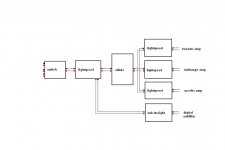
I showed a fullblown preamp fore controlling a big triamped system
I will probably put it aside fore a while, and just do the simplest "passive", with 2 line in, and one out, which is all I need at the moment
Thanks for doing this
Re: Lightspeed remote control
Thanks, I think I understand now
Your VCCS is about IC control of the LDR, instead of the stereo pot
The ideal partner fore remote
Ahh, which would mean no 5V supply needed fore LDR, or ?
Voltage controlled component, stupid
maximus said:Hi Tinitus,
I have provided address programming, on the transmitter and receiver boards, for up to 4 separate receiver boards (only one transmitter board required) so you can set up your system as you wish.
Regards
Paul
Thanks, I think I understand now
Your VCCS is about IC control of the LDR, instead of the stereo pot
The ideal partner fore remote
Ahh, which would mean no 5V supply needed fore LDR, or ?
Voltage controlled component, stupid
Re: Lightspeed remote control
Hang on
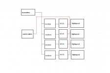
Does this mean I can drive 4x LDR(stereo att) simultaniously
And additionally still have individual fine adjustment of each LDR att
But I suppose I would need 4x VCCS and 4x receiver, one each LDR stereo att
The trick of this is that the LDR is ok to have on the OUTPUT of a preamp
And the gain unit could be seperate, and easily removed or changed
Well, a bit expencive, but also very interesting 😎
maximus said:Hi Tinitus,
I have provided address programming, on the transmitter and receiver boards, for up to 4 separate receiver boards (only one transmitter board required) so you can set up your system as you wish.
Regards
Paul
Hang on
Does this mean I can drive 4x LDR(stereo att) simultaniously
And additionally still have individual fine adjustment of each LDR att
But I suppose I would need 4x VCCS and 4x receiver, one each LDR stereo att
The trick of this is that the LDR is ok to have on the OUTPUT of a preamp
And the gain unit could be seperate, and easily removed or changed
Well, a bit expencive, but also very interesting 😎
Attachments
Lightspeed remote control
Hi Tinitus,
You will need a 15 volt DC supply to power the VCCS module.
You would need eight IR Receiver modules to run four parallel VCCS modules. Four receiver modules would have the same programmed address which would allow the transmitter to control all VCCS modules at once, and a further four receiver modules individually parallelled with the first four receiver modules, each with a different programmed address, would give you individual fine control. I can add further program addresses with a little track surgery on the transmitter and receiver modules. One transmitter module in the handset can control one or all of the modules by using a switch to set the address.
Regards
Paul
Salut
Received the pcbs - thanks Paul.
A question before I build that might interest others:
The HT12 tx/rx seem compatible with RF, too. Can I just tag suitable modules in the place of the IR LEDs? Or would something like this be more suitable:
http://electronics-diy.com/product_...ependent ON / OFF or Momentary Relay Outputs (100m)
...with the intention of hiding the attenuator away, of course. Most of my creations never make it to a box, and even when they do they're not that pretty!
@+
Vernon
Re: Lightspeed remote control
Thanks Paul
Gets complicated, and expencive, even if I would use only 3 LDR outputs
I will just build with single LDR unit, fore now
And take up the 3x output later
But its only good fore passive triamped speaker design
Adding say a digital/eq/crossover, and its all down the drain
Something I need to think about
To others
Click at Pauls pictures of board layout(post 2143), and you will find some photos that shows how neat the VCCS really is, with onboard LDR
maximus said:Hi Tinitus,
You would need eight IR Receiver modules to run four parallel VCCS modules.
Paul
Thanks Paul
Gets complicated, and expencive, even if I would use only 3 LDR outputs
I will just build with single LDR unit, fore now
And take up the 3x output later
But its only good fore passive triamped speaker design
Adding say a digital/eq/crossover, and its all down the drain
Something I need to think about
To others
Click at Pauls pictures of board layout(post 2143), and you will find some photos that shows how neat the VCCS really is, with onboard LDR
Lightspeed remote control
Hi Vernon,
The world is your oyster regarding transmission medium. I only made the IR system available because this is what I was using and I was asked to provide it by constructors. You could use an RF system instead of the IR system. I have not investigated RF remote control so cannot offer circuit guidance. Unfortunately I am too busy to research the subject at present.
Whatever system you use, the receiver circuit must be able to operate on the floating 5 volt shunt regulator powering the DS1802 and it's output terminals must be able to connect the DS1802 control pins (16-19) to the DS1802 AGND pin (14) to initiate a response. The receiver switch action must be momentary.
Hope this helps. 🙂
Regards
Paul
- Home
- Source & Line
- Analog Line Level
- Lightspeed Attenuator a new passive preamp