I wonder why it is not done then? Stepped attenuators and good old fashioned pots seem to prevail, even in high-end stuff...
I've never seen an implimentation of my idea in any piece of audio equipment (but I clearly have not seen them all!)
It's mostly a hobby build thing, with some small guys selling them. The LED/LDR has been used in pro audio compressor stages and elsewhere for a long time.
Just search on silonex nsl-32sr2 for data sheets and app notes. You can buy them for $2. and sort/match them to build your volume control. Also see the lightspeed thread, which goes back 4-5 years...
It was silly of me to look at the latest design, but my curiosity overcame my better judgement. Needless to say it is just as barmy as his earlier designs. Should subjecting opamps to cruel and degrading treatment be allowed?Chris Daly said:Latest schematic attached,
It was silly of me to look at the latest design, but my curiosity overcame my better judgement. Needless to say it is just as barmy as his earlier designs. Should subjecting opamps to cruel and degrading treatment be allowed?
I think you grossly misunderstand the function / excellent feature, of a op amp that will not allow current in to its inverting input.
As I understand the op amp simply enjoys converting this provision ( no more than inherent ) as conversion to a voltage at the op amp output to maintain equilibrium.
Cheers / Chris
It was silly of me to look at the latest design, but my curiosity overcame my better judgement. Needless to say it is just as barmy as his earlier designs. Should subjecting opamps to cruel and degrading treatment be allowed?
For what it's worth, on the last go round, I built the mini version of this circuit, w/ pics as posted before.
I thought the reason the transistors as diodes were needed on the - input was because the TL-072 is not a rail to rail op-amp. Quick sidebar, usually you need to use a "rail to rail" op-amp if you use a single polarity supply (i.e ground the minus supply side), *and* the design calls for using any of the inputs or outputs very close to ground.
It seemed to fit, that the diodes biased the - input above ground.
That was not proven true. I inserted a true "rail to rail" dual op-amp into the breadboard version, and the circuit no longer worked at all. The LEDs did not light any any volume position.
Yes, it is a cruel misuse of op-amps, and other parts, that is specific to the TL-072, maybe others, who knows?
Having all 4 op-amp outputs summed and feeding the voltage regulator *input* is, to me, the oddest thing I have ever seen in a published circuit.
As said before, the voltage regulator by design ignores any changes to the input above cutoff.
If operated below cutoff, why even bother having it?
Wow, this is quite a radical departure to do the current steering from the grounded side of the LEDs! It looks like you forgot the 22K resistors though, or are they no longer beneficial with this revision of the circuit?Latest schematic attached,
Cheers / Chris 🙂
It was silly of me to look at the latest design, but my curiosity overcame my better judgement. Needless to say it is just as barmy as his earlier designs. Should subjecting opamps to cruel and degrading treatment be allowed?
For what it's worth, on the last go round, I built the mini version of this circuit, w/ pics as posted before.
I thought the reason the transistors as diodes were needed on the - input was because the TL-072 is not a rail to rail op-amp. Quick sidebar, usually you need to use a "rail to rail" op-amp if you use a single polarity supply (i.e ground the minus supply side), *and* the design calls for using any of the inputs or outputs very close to ground.
It seemed to fit, that the diodes biased the - input above ground.
That was not proven true. I inserted a true "rail to rail" dual op-amp into the breadboard version, and the circuit no longer worked at all. The LEDs did not light any any volume position.
Yes, it is a cruel misuse of op-amps, and other parts, that is specific to the TL-072, maybe others, who knows?
Having all 4 op-amp outputs summed and feeding the voltage regulator *input* is, to me, the oddest thing I have ever seen in a published circuit.
As said before, the voltage regulator by design ignores any changes to the input above cutoff.
If operated below cutoff, why even bother having it?
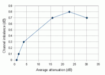
Measured L and R channel difference at three volume settings no input and output load
Low
Shunt L 412R Shunt R 362R
Series L 13.43K Series R 10.84K
Aggregate 13.84K 11.2K
Difference 2640 ohms
Medium
Shunt L 7.38K Shunt R 7.08k
Series L 4.20K Series R 3.60k
Aggregate L 11.58K R 10.68k
Difference 900 ohms
High
Shunt L 14.02K Shunt R 13.75K
Series L 1437R Series R 1317R
Aggregate L 15.45 R 15.06K
Difference 390 ohms
Cheers / Chris
Nah, Bud's stuff is way more Zen. You can't beat this circuit for simplicity; one wire, one connection, that's it. Needless to say, the effect on perceived sound quality is not insignificant.oddest thing I have ever seen in a published circuit.
.
Attachments
Wow, this is quite a radical departure to do the current steering from the grounded side of the LEDs! It looks like you forgot the 22K resistors though, or are they no longer beneficial with this revision of the circuit?
No the 22K is not needed, the volume adjustment is quite gradual. For curiosity a resistor of suggest 33k similarly placed from mutual anode upper connection of potentiometer to ground gives a pronounced slow startto volume adjustment.
Voltage up slightly too off the LM317 adding another 220 ohms ie 1.25 x 220/740 +1 V out = 5.45v appears to improve L / R measured balance. Vout of current setting LM317 then varies 3.91 at min and max, and to 4.80v approx 3/4 volume.
Cheers / Chris 🙂
The attenuation works out to:Measured L and R channel difference at three volume settings...
Low
Left: 30.5dB Right: 29.8dB
Medium
Left: 3.9dB Right: 3.6dB
High
Left: 0.8dB Right: 0.8dB
That looks pretty good. Most of the action is between "Medium" and "Low". It would be interesting to see another measurement inbetween those.
I like that the input impedance stays sensible, between about 10K to 15K. 🙂
The effectiveness of that depends on circuit design. Of course, without full knowledge of the circuit it is used with, there are many uncertainties. There are also other things that can be done to have similar improvements.Nah, Bud's stuff is way more Zen. You can't beat this circuit for simplicity; one wire, one connection, that's it. Needless to say, the effect on perceived sound quality is not insignificant.
.
Over here, we will see similar communication between the Chinese medicine doctors and the common medicine practices.😀 Personally I see pros and cons in either practice. Just yesterday, I saw a report on TV (Boomberg) about the cause of metabolism disorders from sleeping disorders, late night shifts, little sleep at night etc. which also cause slow down of metabolism as well. This knowledge has been there for a very long time. So we had a good laugh.
The attenuation works out to:
Low
Left: 30.5dB Right: 29.8dB
Medium
Left: 3.9dB Right: 3.6dB
High
Left: 0.8dB Right: 0.8dB
That looks pretty good. Most of the action is between "Medium" and "Low". It would be interesting to see another measurement inbetween those.
I like that the input impedance stays sensible, between about 10K to 15K. 🙂
Between those;
Low/Medium
Shunt L 659R Shunt R 595R
Series L 8.87K Series R 7.22k
aggregate L 9..52K R 7.81k
difference 1710 ohms
Below Medium
Shunt L 1370R Shunt R 1244R
Series L 7.39k Series R 6.10k
aggregate L 8.76K R 7.34K
difference 1420 ohms
Above medium
Shunt L 8.58k Shunt R 8.41k
series L 1913R series R 1700R
aggregate L 10.49k R 10.11K
difference 380 ohms
Cheers / Chris 🙂
Collated results:
Low
Left: 30.5dB Right: 29.8dB
Low/Medium
Left: 23.2dB Right: 22.4dB
Below medium
Left: 16.1dB Right: 15.4dB
Medium
Left: 3.9dB Right: 3.6dB
Above medium
Left: 1.7dB Right: 1.6dB
High
Left: 0.8dB Right: 0.8dB
Interestingly, a bit of fooling around on a calculator shows that channel balance can be improved a lot just by adding a 100K resistor in parallel with the left series LDR. That obviously only applies for these specific LDRs, but it suggests that it may be possible to tweak individual attenuators very nicely if space is left on the PCB for a few optional resistors.
Pic below shows the raw results (without the 100K resistor).
Attachments
Collated results:
Low
Left: 30.5dB Right: 29.8dB
Low/Medium
Left: 23.2dB Right: 22.4dB
Below medium
Left: 16.1dB Right: 15.4dB
Medium
Left: 3.9dB Right: 3.6dB
Above medium
Left: 1.7dB Right: 1.6dB
High
Left: 0.8dB Right: 0.8dB
Interestingly, a bit of fooling around on a calculator shows that channel balance can be improved a lot just by adding a 100K resistor in parallel with the left series LDR. That obviously only applies for these specific LDRs, but it suggests that it may be possible to tweak individual attenuators very nicely if space is left on the PCB for a few optional resistors.
Pic below shows the raw results (without the 100K resistor).
Thank you, Cheers/ Chris
Is this another Turing test? If I can extract any meaning from these 'English sentences' then that proves I am not a bot?Chris Daly said:I think you grossly misunderstand the function / excellent feature, of a op amp that will not allow current in to its inverting input.
As I understand the op amp simply enjoys converting this provision ( no more than inherent ) as conversion to a voltage at the op amp output to maintain equilibrium.
I wonder if this relatively good channel balance is the result of current driving or some other perchance good luck?Collated results:
Low
Left: 30.5dB Right: 29.8dB
Low/Medium
Left: 23.2dB Right: 22.4dB
Below medium
Left: 16.1dB Right: 15.4dB
Medium
Left: 3.9dB Right: 3.6dB
Above medium
Left: 1.7dB Right: 1.6dB
High
Left: 0.8dB Right: 0.8dB
Interestingly, a bit of fooling around on a calculator shows that channel balance can be improved a lot just by adding a 100K resistor in parallel with the left series LDR. That obviously only applies for these specific LDRs,
Or is it because we can't see the balance @ -40dB and -50dB and -60dB?
Last edited:
Not at all. I may be a little stoned right now as I was looking at one of BudP's threads last night and the effects tend to linger, but it does put one in a more appropriate state of mind to appreciate this sort of thing.Is this another Turing test?
Alchemy and mysticism aside, no effort is being made here to equalize the LED currents between channels so luck and/or device matching, I guess. If I was building an LDR attenuator, I think I'd be happy if I could get 40dB control range without seriously compromising anything else.I wonder if this relatively good channel balance is the result of current driving or some other perchance good luck?
Or is it because we can't see the balance @ -40dB and -50dB and -60dB?
Normally 0~60db range is the evaluated range. Traditionally the amp as about 26db or more gain, and the preamp has 10db gain.
I wonder if this relatively good channel balance is the result of current driving or some other perchance good luck?
Or is it because we can't see the balance @ -40dB and -50dB and -60dB?
I've been playing around with these things, and getting decent matching to -30 dB is pretty easy. Decent meaning better than .3 dB mismatch.
It get much harder to maintain that at -45 to -60dB, even further harder at -90dB.
But what is interesting, once you have the data, is being able to try (in excel) different combinations of series and shunt on L and R, to get the best results.
I use 10 points now, but realize I need more in the middle, will take it to 12.
Last edited:
Here's some data from reading on Silonex NSL-32SR3 unit. I measured 20 of them, 3 at a time.
I labeled the units 1 through 20, then sorted them in excel by ohms.
Which current point you use to sort on is up to you. This is one example that sorts on 0.5ma LED current, and you can see the spread from 306.5 to 541 ohms over the 20 units.
I labeled the units 1 through 20, then sorted them in excel by ohms.
Which current point you use to sort on is up to you. This is one example that sorts on 0.5ma LED current, and you can see the spread from 306.5 to 541 ohms over the 20 units.
Attachments
- Status
- Not open for further replies.
- Home
- Source & Line
- Analog Line Level
- Light Dependant Resistor Current Control