The TO-92 devices are bare BC327 and BC337 from On-Semi, rated at 1A peak. The gaps are 3.2mm but should actually be 6mm in the center leg only. That's the only way to get 200uH 30A in a reasonable size, as toroid cores are just not up to the job and can hardly handle a +/-170V input square wave due to too high losses. By the way, the magnetic field from the gap is causing a lot of trouble in the windings, as it shifts high-frequency current flow to the most outer layers of the magnet wire, thus increasing apparent resistance dramatically and causing a lot of copper heating in the turns near the gap independently of load current.
Eva, have you try the 3F3 or 3F4 material in toroid shape? This should give the result your looking for, without the probleme of dV/dt with ''standard'' output coil material...
Fredos
www.d-amp.com
Fredos
www.d-amp.com
Thanks Eva!
Eva, what do you think of using BCX53/56 as mosfet-drivers? Are they suitable for this position?
I saw both types' (BC and BCX) datasheet, i think theee BCX transistors not as good as thoose BC327/337 in this position. Am I right?
Eva, what do you think of using BCX53/56 as mosfet-drivers? Are they suitable for this position?
I saw both types' (BC and BCX) datasheet, i think theee BCX transistors not as good as thoose BC327/337 in this position. Am I right?
RX5,
The circuit you posted #261 will basically do what you intended. I do have a couple of comments. Of course a level shifter is needed. The trianlge wave is just what you need, so that's fine. C9 needs to be chosen such that the charge on it is much greater than the gate charge of the MOSFET. I didn't do the calculations, but it seems low. R38 is way too small. You need to do the calculations for all component values to confirm they are appropriate. A quick mental assessment indicates there is room for improvement/optimization of the values.
Rick
Fredos you should be kidding. 3F3 and 3F4 are high frequency high permeability power ferrites, so they can't store any energy unless they are gapped. Toroids are not suitable for gapping, and if they are manually gapped by cutting a small slice, there is no way to control the resulting stray magnetic fields. On the other hand, E cores can be gapped in the center leg, leaving the windings acting as a shield thus producing very little stray magnetic fields.
Also, the trouble that I'm experiencing is related to copper losses due to skin and proximity effects, it's not related to core losses. The N67 material that I'm employing is fine. That's why I asked for litz wire sources.
Danko don't be too shy. Damn, are you telling me that you don't know how to choose a bipolar transistor for an emitter follower application? Find out how much peak gate currents do you need and then find a pair of transistors capable of handling them with reasonable gain 😉
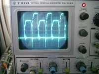
Now i have a working D-amp again!!😀
It´s too late to test it thoroly but it sounds good on the low volume i have now.
I´ll be back tomorrow with pics and scope shots.
It´s too late to test it thoroly but it sounds good on the low volume i have now.
I´ll be back tomorrow with pics and scope shots.
Hi, RX5.
Do you still interested to build DIY class D or not? My suggesttion is better you try self oscillation class D = UcD DIY. It shall enough for you. Why use that complex for that power level?
Over 100W output you shall spent enough money and order a fresh component that you must larn more new component and circuit behaviour. Not easy to make good triangle generator and not easy suitable component too. And you shall use scope of course. The other problem is what Fredos, Kanwar and Chris talked. Higher voltage, lots of destructive phenomena that shall be considered.
Best regards,
Kartino
sawreyrw said:RX5,
The circuit you posted #261 will basically do what you intended. I do have a couple of comments. Of course a level shifter is needed. The trianlge wave is just what you need, so that's fine. C9 needs to be chosen such that the charge on it is much greater than the gate charge of the MOSFET. I didn't do the calculations, but it seems low. R38 is way too small. You need to do the calculations for all component values to confirm they are appropriate. A quick mental assessment indicates there is room for improvement/optimization of the values.
Rick
Ok... nice to hear it will work... and i know it will... just as kartino said, i got 3 reference points to tie to.... GND, the Source of Hi side mosfet and the Source of Lo side mosfet.... 🙂
kartino said:Hi, RX5.
Do you still interested to build DIY class D or not? My suggesttion is better you try self oscillation class D = UcD DIY. It shall enough for you. Why use that complex for that power level?
Over 100W output you shall spent enough money and order a fresh component that you must larn more new component and circuit behaviour. Not easy to make good triangle generator and not easy suitable component too. And you shall use scope of course. The other problem is what Fredos, Kanwar and Chris talked. Higher voltage, lots of destructive phenomena that shall be considered.
Best regards,
Kartino
I will try chris's mini UcD... 🙂 and if all goes well, ill try to figure out a way into making it bridgable.. if I can.. hehehe and as i have noticed from the past post, iv seen 2 feedback points.. single ended has one.. 🙂
take care all....
oooppps another prob??
how do i levelshift the Lo side?? invert 1st then levelshift using -V as my reference??
i think much easy to level shift in the Hi side because its referenced to Hi side mosfet Source.. w/c is GND....
am i correct??
how do i levelshift the Lo side?? invert 1st then levelshift using -V as my reference??
i think much easy to level shift in the Hi side because its referenced to Hi side mosfet Source.. w/c is GND....
am i correct??
High side MOSFET source is not at ground potential, it's floating as it's connected to the switching node!
Hi RX5,
Some people made the DIY UcD as well done. If you copy exaclty to real circuit then it shall work.
The high side as Eva said referenced to floating point. The low side referenced to negative rails. The audio referenced to each other between inverted and non inverted input. You can connect the ono inverted input to ground if your tone control referenced to ground.
regards,
kartino
Eva!
Losses in copper are the lowest with drum cores - if you can keep it away from any other metal parts. I had the same task (100 kHz +/-30 A, +/-150 V output), but I was afraid of stray magnetic field so I still use arnold's iron powder cores (4 pieces for 50 uH) with forced cooling.
Thanks for the idea of grounding one output of bridge! It is working now, and thanks to direct current sensing output current noise is under 30 uA. (With LEM current sensor it was 10 mA.)
Do you need litz wire for prototyping only? I can give limited amount of 160*0,1 mm or ~70*0,2.
Attachments

Hi Eva
Sounds like a very interesting project you're running.
In post #181 it sounded like you where running half bridge, but I think I read in another post that you are using a rectified mains of 340 VDC to run a H bridge output stage. Is that correct?
What is your switching freq. 100 kHz?
What IGBTs are you using?
Haven't you had any problems with running on single layer boards only, and using through hole components? (parasitics and GND) .... but maybe it isen't so much a problem at 100 kHz!
If you are running on an H-bridge of 340 VDC you should be able to get more than 7 KW in 8 ohm!!!! How far have you tryed to go?
What is the distortion level of your circuit? (I know it's not intended for Audio, but you have indicated that it works weel enough for that purpose 🙂)
Keep up the good work 😉
Hi Pafi
Toroids are suitable for 50uH 30A, but I need at least 200uH 30A, which implies over 90mJ energy storage. I don't expect any iron powder core with a diameter equal or below 50mm to store more than 10mJ, or should I? On the other hand, a strongly gapped E42 can store almost 50mJ, and when the gap is in the center leg, the worst-case induced voltage on a 10cm diameter loop of wire placed near the inductor is only a dozen milivolts or so. The only problem is that the turns in the region of the air-gap are subject to very strong skin and proximity effects.
Concerning litz wire, please mail me. The sizes that you mentioned are almost what I'm looking for.
Baldin:
Initially the prototype was half bridge with a capacitive divider on the other side to make things simpler. Now I'm laying out a full bridge PCB. My PCBs are now double sided with gentle ground planes, but I don't have SMD or hole plating facilities. IGBTs are SKP10N60. Intended operating frequency is 50Khz for the lowest losses, altough I may have to rise it to 100Khz. I have not performed any distortion measurements.
Hi Fredos,fredos said:Hello Guy
Add diode in serie with the mosfet add voltage drop to the leg and by the way drop the effiency of the amplifier....
For all other who try to work with level shifter: Look at schematics I post fews thread before with Circad...I have find the solution 7 years ago...Simply use a fast 2N4401 or 2N4403, depend of your need with a zener diode to drop the excess voltage you need to drop! That's fast, efficient and cheap!
Fredos
www.d-amp.com
Adding series Schottky would just add a voltage drop of 0.4V MAX and with rails at +-120VDC , it seems negligible and regarding the efficiency it would not also decrease to that extent with just 0.4V drop...
But it surely makes the output stage much more robust.....
Regarding Zeners for excess voltage drop, they seems to be good idea but again they also cause the same dissipation as compared to the resistors provided the same value of voltage drop by both Zener and Resistor......
TOINO said:Hi Workhorse
In your post 242 the Schottky is only 20V but works in an environment of 250V….
This is not dangerous? (For the diode?)
Hi Toino,
Dont you see that the Schottky is protected from reverse potential by the Antiparallel HEXFRED diode with Vf=0.6V
Cheers,
K a n w a r
Once again, I can only reccomend Olimex.
It's cheap, fast and good. $33 USD for a double sided euro card.
They do panelisation at no extra cost, and they even accept Eagle files 🙂
It's cheap, fast and good. $33 USD for a double sided euro card.
They do panelisation at no extra cost, and they even accept Eagle files 🙂
- Status
- Not open for further replies.
- Home
- Amplifiers
- Class D
- level shifters and mosfet drivers