can these 2 circuits be joined??
Hi all,
I dunno if possible but....
above circuit , self oscillating.....
combined with discrete driver...shown bellow..
will it work?? 😀 i mean, does it lack someting else?? im guessing maybe a lever shifter in between op-amp and transistor drivers??
Hi all,
I dunno if possible but....
An externally hosted image should be here but it was not working when we last tested it.
above circuit , self oscillating.....
combined with discrete driver...shown bellow..
An externally hosted image should be here but it was not working when we last tested it.
will it work?? 😀 i mean, does it lack someting else??
im guessing maybe a lever shifter in between op-amp and transistor drivers??You need a comparator with a separate GND for the output part so you can reference the comparators output to gnd, then you need a level shifter so yoiu dont need to reference everything to the neg rail, then a level shifter for the high side input. Here you can use a fast optocoupler for levelshifter.
First the schematic is not self oscillation beause there is triangle generator.
Second the Hi - Low signal of the input stage referenced to ground (0) and the UcD output stage the Hi referenced to floating point and the Lo referenced to negative rail.
If you are smart you can see that the complete UcD without Op Amp Ic and feedback network has inverting input and non inverting input that referenced to ground. I did not make simulation yet but it is possible. I see analogspiceman use his leapfrog combined with UcD for output stage.
Sorry can't help you completely.
Best regards,
kartino
darn.. i thought it was possible.. whew....
what was i thought simple , is getting more complex.. hehe
what was i thought simple , is getting more complex.. hehe
Hello Guy
WorkHorse: The ES1D diode have the same voltage drop than the body diode of mosfet, and yes handle only 1 Amp, but was lot faster than the body diode of the mosfet. That's why I use it, only for the fews ns of the switching, when body diode can ''clip'' the small ringing of the PCB layout. After this, the body diode handle all the reverse power of freewheling. Add diode in serie with the mosfet add voltage drop to the leg and by the way drop the effiency of the amplifier....
For all other who try to work with level shifter: Look at schematics I post fews thread before with Circad...I have find the solution 7 years ago...Simply use a fast 2N4401 or 2N4403, depend of your need with a zener diode to drop the excess voltage you need to drop! That's fast, efficient and cheap!
Fredos
www.d-amp.com
Fred,
If I understand I'm not sure that I do fully, you're using the // diode to help with the little glitch seen at zero cross over, and aren't at all concerned with the reverse recovery time. Is this correct? This points to the glitch being more due to the gate activity..?
Forward diode drops are not at all constant though, so I was saying it may be well worth that extra hit in efficiency, and gain every advantage of removing the non constant variables .... and also entirely do away with the slow recovery time.
Comments on that?
"Simply use a fast 2N4401 or 2N4403, depend of your need with a zener diode to drop the excess voltage you need to drop! That's fast, efficient and cheap!"
That's another alternative and one I thought of last night... I wouldnt' use a dissipative resistor either. Still there are other ways, people ought to research them. Even this is not ideal, but much better.
4sure, did you find out why my/workhore´s circuit melted down your breadoard ? You are welcome to insult me if i made any errors in the ugly paint schemo.
Yes classd4sure, the ES1D only ''take care'' of the fews first nS of switching, then after the body diode do the rest of the job. I know that this will be hard to figure with simulation or without have try it, but that's really work well. This do the same job as the workhorse circuit, but more efficient.
For long time I use zener as a non-dissipative element in my level shifter, even at +/- 150V, but with separated zener to split the ''small'' dissipation of the zener at this voltage. In that way, you can use fast low voltage transistor in the level shifter stage.
Fredos
For long time I use zener as a non-dissipative element in my level shifter, even at +/- 150V, but with separated zener to split the ''small'' dissipation of the zener at this voltage. In that way, you can use fast low voltage transistor in the level shifter stage.
Fredos
Hi Fred,
It seems to be not the same entirely. From what I gather if I'm following this properly, you're more concerned with the first few nS of switching, while the turning off of the body diode, is more for the concern of the last few seconds.
Since you allow the body diode to conduct, and fully at that, you're then relegated to the use of the fredfet, or it's useless. The combination of the two may give the same performance, but I still think what workhorse posted is the more robust solution by far.
Just goes to show you how pointless it is go give people readymade solutions to problems they haven't come to understand yet, all things being application specific, they're going to plug them in and scratch their heads when it doesn't work as expected.
I do like the idea of the zener, nice to know it can work very good, I will lock it into memory as yet another possibility for future usage 🙂
This is finally becomming an interesting hardware thread 🙂 It never was before. BTW, since when are zeners non dissipative 😉
I admit Fred, I like giving you a hard time 😀
PS:
I think it's a far better solution than the usual medium power video amplifier!~
Yeah, but if it worked right it should have been fine, it almost takes them glowing red before it begins to soften the plastic. Are you sure it's not something with the circuit?
Hi Workhorse
In your post 242 the Schottky is only 20V but works in an environment of 250V….
This is not dangerous? (For the diode?)
In your post 242 the Schottky is only 20V but works in an environment of 250V….
This is not dangerous? (For the diode?)
Melted breadboards?? Fire?? Ouch! 😀😀😀😀
When building new stuff, care has to be taken to go step by step, checking every part of the circuit to work as expected in order to prevent these disasters.
Concerning the diode stuff, when it comes to switch more than a couple hundred volts, MOSFETs become very clumsy devices, while modern co-packed SMPS IGBTs excel. They are completely free from that body diode crap, while they include a built-in hyperfast soft-recovery diode instead.
Also, those tales about slow switching and current tails have become mostly urban legends. In my prototype, the turn-off Vce of the IGBTs is rising to 500V in less than 50ns under load, and turn-on crossover time is also in the 50ns range. Surprisingly, I have noticed that when the circuit is idle the heatsink is actually cooler at 100Khz than at 50Khz because conduction losses from output inductor current ripple dominate, and they are halved at 100Khz.
BTW: Tekko, things are much easier when you have a robust gate drive circuit with built-in dead time and a single HI/LO input (and an "enable" jumper that you can remove while you play with the modulator breadboard), like the one on that daughter board:
Attachments
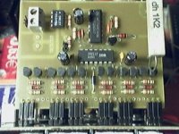
Eva, but IR2111 can only do a few 100 mA out and it has alittle too mutch deadtime for class d as it is intended for smps.
I am not sure if it can turn the fets on/off enough not to cause cross conduction or close enuf to saturation.
I am not sure if it can turn the fets on/off enough not to cause cross conduction or close enuf to saturation.
Eva,
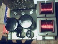
Is that the controller section for your multi-kilowatt power converter? Would you be interested in posting pictures of the power section with the IGBT and capacitors? I'm interested in seeing how you did your layout as you have helped me with my troubles in the past 🙂 Cool project by the way!
Thanks!
-=Randy Knutson
Mankato MN
Tekko,
IIRC I don't think she's building an audio amplifier, but some type of power inverter that converts 340AC to something like +/-130V 30Amps.
Its true that the IR2111 can only output 100mA but look at the picture more closely- she is using NPN and PNP transistors on the output of the IR2111 to increase the maximum current.
-=Randy Knutson
Mankato MN

- Status
- Not open for further replies.
- Home
- Amplifiers
- Class D
- level shifters and mosfet drivers