I just wanted to point out how much grid current is already dominated by internal soft x-rays, and how little is due to other causes like gas or grid contamination. Elevated grid current levels must be due to very gross defects in the valve. It seems to me that Weijer's suggestion of 'charged dust' getting clogged on the grid (if it did exist) would be be negligible compared with gas evolution and grid contamination due to natural cathode evaporation, both of which are proven effects, and ultimately unavoidable.
This statement, and the conclusion you draw from it, make no more sense than the previous post. Production of X-ray originated current sounds more probable in kV operated Xray, microwave, or transmitting devices - but in a 300-500v setup?
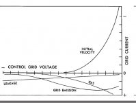
For a realistic breakdown of the origin of "normal" grid current at receiving tube voltages, see the curves on page 27 of Tomer (kindly hosted online by Pete Millet):
Technical books online
Attachments
Thanks again, Rod.
In my PSU the rectifiers heaters are coming slow with the aid of thermistor. Since the amp tubes are also coming slow, it looks to me like good enough.
In my PSU the rectifiers heaters are coming slow with the aid of thermistor. Since the amp tubes are also coming slow, it looks to me like good enough.
Last edited:

Here is updated PSU schematic.
That looks good.
Some fine tuning may be worthwhile with the big caps on the heater dc. The LM3xx chips will give pretty good ripple rejection, provided they have enough headroom. Then you can reduce the C value, in order to keep the peak currents low.
If the heater takes 1.5A dc, the caps must withstand a ripple current of at least 3A to maintain reliability, and this is the parameter I'd use to select a capacitor in this position. The output ripple doesn't matter very much, and of course they work acceptably on a ripple of 6.3V! Keeping the C value low reduces the stress on the other parts, and also reduces any EM-coupling of the ampere-level cap recharge pulses into any other parts of the circuit.
This is not a first-order effect to consider, especially if you have well-rated rectifier & trafo.
Thanks, Rod.
The power trafo's secondary windings for the rectified heaters will be rated at twice the current of the heaters. As for the actual caps make and value – yes, they'll have to be considered. The values mentioned right now are definitely not final. Anyhow, you are right by pointing that lower values are preferred. Of course, some ripple on the heaters is no issue at all, however, when all else is equal, I prefer lower ripple.
The power trafo's secondary windings for the rectified heaters will be rated at twice the current of the heaters. As for the actual caps make and value – yes, they'll have to be considered. The values mentioned right now are definitely not final. Anyhow, you are right by pointing that lower values are preferred. Of course, some ripple on the heaters is no issue at all, however, when all else is equal, I prefer lower ripple.
Production of X-ray originated current sounds more probable in kV operated Xray, microwave, or transmitting devices - but in a 300-500v setup?
For a realistic breakdown of the origin of "normal" grid current at receiving tube voltages, see the curves on page 27 of Tomer (kindly hosted online by Pete Millet):
These are soft X-rays (long wavelength), which are indeed produced at low voltages.
Tomer's curves are essentially the same as that given in RDH4 (1953) and date back to the days when they still assumed the reverse grid current was predominantly due to gas ions, which is incorrect,as the later literature shows. (Tomer's book is useful, but not really high-brow stuff. He makes another gas error somewhere as I recall).
Metson et al's paper was published late 1952, obviously too late to alter the contents of RDH4. Also of interest is: Farstein, Grid Current in Electron Tubes. RSI, June 1958.
"The first two sources of electron emission [primary and photoelectric] always can be made negligibly low by operating the cathode at a sufficiently low temperature and by shielding the tube from external light... The third source [photoelectric emission due to X-ray and UV] cannot be eliminated although it can be reduced by low current and low voltage operation of the tube."
"It has long been assumed that ionized gas is the main source of grid current...There is now little doubt that the observed grid current is due mainly to photoelectric emission from the grid, the photons and x-rays being produced at the plate."
Incidentally they were studying small receiving valves up to 200V, including the "recently announced E88CC"! It's well worth a read.
Last edited:
These are soft X-rays (long wavelength), which are indeed produced at low voltages.
Metson et al's paper was published late 1952, obviously too late to alter the contents of RDH4. Also of interest is: Farstein, Grid Current in Electron Tubes. RSI, June 1958.
"The first two sources of electron emission [primary and photoelectric] always can be made negligibly low by operating the cathode at a sufficiently low temperature and by shielding the tube from external light... The third source [photoelectric emission due to X-ray and UV] cannot be eliminated although it can be reduced by low current and low voltage operation of the tube."
"It has long been assumed that ionized gas is the main source of grid current...There is now little doubt that the observed grid current is due mainly to photoelectric emission from the grid, the photons and x-rays being produced at the plate."
That is very interesting.
It also says "the tubes were operated on the plateau of grid current vs heater voltage" but unfortunately does not record what the actual heater voltages were.
The experimenter then records grid current for a selection of valves, including (at 100v and 10mA) the E180F at about 1nA.
This compares to the E180F data sheet value of 500nA max (initial) and 1uA max at end of life - all consistent with the max. rating of 250K for the (fixed bias) grid resistor.
As you already noted, the author writes:
"The first two sources of electron emission [primary and photoelectric] always can be made negligibly low by operating the cathode at a sufficiently low temperature "
The only reasonable conclusion one can take is that the experiment was conducted with underheated valves, despite the E180F data sheet warning that "Vf below 6.0V shortens tube life"
Philips clearly specified that 0.5 to 1uA of grid current must be accommodated in the E180F, in a practical circuit. Fairstein gives no hint at the discrepancy between this and the pA to nA results in his paper.
More interestingly he does concede that "grid emission worsens as a tube ages because of the cathode material deposited at the grid", so are we to assume that this becomes the dominant grid current? Something is clearly overtaking the third-level effects over the service life of the cathode.
SO when you say:
"It has long been assumed that ionized gas is the main source of grid current...There is now little doubt that the observed grid current is due mainly to photoelectric emission from the grid, the photons and x-rays being produced at the plate."[/i]
This is an observation that applies only in experimental conditions rigged to eliminate the usual effects, and when the actual grid current is in the pA level.
Highbrow papers are interesting and educative, but translating their meaning into practical design work is a hazardous affair.
That is an interesting discrepancy. You are right that it would have been useful to know the heater voltage used, as that may well have something to do with it. If the heater voltage were low, then the normal operation assumed by the datasheet would increase the grid primary emission. (Although it would need to be a lot of emission to increase it by a factor of 100 over the base photoelectric level!)This compares to the E180F data sheet value of 500nA max (initial) and 1uA max at end of life - all consistent with the max. rating of 250K for the (fixed bias) grid resistor.
Hi all
how about in Tv picture tube? I remenber about some tv picture tubes are going with poor emission and we could see the effects in the picture! and we had a tube rejuvenator that worked pretty well! Could we do the same with an EL34 ? And the TVs dont use any Delay for filaments and for the HT! As far as i know!
When rejuvenatig a picture tube ,i could see inside some sparkling? what was that? Cathode contamination?
Thanks
Silvino
I don't understand how rays emanated by anode and light coming outside can ionize grids, but believe that they can ionize gases.
It's called the photoelectric effect:I don't understand how rays emanated by anode and light coming outside can ionize grids,
Photoelectric effect - Wikipedia, the free encyclopedia
Come to think of it, the hotter the cathode (and therefore grid) the lower the work function of the grid, which would increase the effect.
It's called the photoelectric effect:
Photoelectric effect - Wikipedia, the free encyclopedia
Come to think of it, the hotter the cathode (and therefore grid) the lower the work function of the grid, which would increase the effect.
I know what photoemission is, and I remember photomultipliers that had big enough area of cathode coated by special fotoemissive coating, anyway output from them was very weak. Compare to thin clean grid wires in triodes and pentodes, shielded by anodes from an external light.
I don't understand how rays emanated by anode and light coming outside can ionize grids, but believe that they can ionize gases.
The Fairstein paper does suggest that this is direct photon bombardment of the grid. The work function of most valve-making materials (except Barium) would need UV to cause emission, so I imagine that's what he is claiming. This current level is not given a value in the paper, but must be low levels of pA, given the ~100pA level measured, due to photons generated by Anode bombardment by normal anode current.
Fairsteins experiment was:
- operate tubes at reduced heater voltage (to eliminate the usual thermionic 'leakage' current)
- test superb new 1958-production valves with no gas-induced grid current (sigh, those must have been the days)
- shield from external light
- examine the behaviour of the remaining grid current (which was now in the pA range, at 100V/1mA test level), in order to determine whether it was photoelectric-emission or (gas) ionization, according to the voltage characteristic.
So anyway, Анатолий, for your low-noise preamp, be sure to run that 6Ж32П with nice light-proof blinds as well as low heater voltage!😎
Compare to thin clean grid wires in triodes and pentodes, shielded by anodes from an external light.
Most grids are made from molybdenum, which has a work function of 4.6eV.
Dividing by planck's constant, the threshold frequency of the photons for is therefore 1.1 E15 Hz, or 270nm wavelength.
This is UVc light, so it is entirely possible for UV and soft X-rays from the anode to cause photoelectric emission. Please check your physics before posting!
(The work function of the copper side rods is 4.7eV, which also has a threshold frequency in the UVc range)
*sigh* Negligible light is getting in, especially if it's in a sealed box... The light come from the anode itself, *inside*the tube.Good question! Is there really much UVc getting in?
so it is entirely possible for UV and soft X-rays from the anode to cause photoelectric emission
*sigh* Negligible light is getting in, especially if it's in a sealed box... The light come from the anode itself, *inside*the tube.
OK, so we're agreed that external UV is not a factor. Now, next step, what is the UV flux due to plate blackbody radiation? effect.
OK, so we're agreed that external UV is not a factor. Now, next step, what is the UV flux due to plate blackbody radiation? effect.
Zero.
The Fairstein paper attempts to show that the UV and higher-energy photons arise from electron bombardment of the anode from the normal (primary, or anode) current.
His approach is that this must be so because of the (grid to anode) voltage-current behaviour displayed.
If that really is true, it gives useful considerations for low-noise design - providing you are prepared to flaunt the data-sheet minimum for heater voltage, and you have a good stock of suitable low-voltage valves, with a good proportion of low-gas examples.
Last edited:
- Status
- Not open for further replies.
- Home
- Amplifiers
- Tubes / Valves
- Lets settle the b+ on cold tubes issue!