... And since the grid is usually driven by a substantial impedance, the driver loading will vary with Anode-to-grid voltage, which will generate another distortion.
The 6CJ3 having 6.5Watt anode dissipation isn't useful as a rectifier for a power amp drawing 240mA at 450V.
Apparently it takes a few hours for ko conditions to be reached, after which the "apparent pressure remained unchanged for indefinite periods of running". What is unclear is whether they mean you have to wait a few hours every time you switch the thing on, or whether the pressure remains constant afer the very first time it is used.If the paper says something useful about long term effects, please post it.
Some data sheets warn that low filament voltage gives shorter life.
There's a lot of good, solid literature from tube manufacturers on that. Low heater voltage means the cathode temperatures are lower than optimum, so emission deteriorates more quickly than normal.
The 6CJ3 having 6.5Watt anode dissipation isn't useful as a rectifier for a power amp drawing 240mA at 450V.
Well, the specification for the GE 6CJ3 shows:
350mA dc is rated. Voltage drop at 240mA is about 15V (see the graph of drops). There are TWO diodes involved in the passing of the 240 mA, so the average current through each is 120mA. Power dissipation is 0.12 x 15= 1,8W.
These dampers are tough, and will last forever at such a low stress level.
Okay, got it. Where can one get sockets for those tubes?
There's a lot of good, solid literature from tube manufacturers on that. Low heater voltage means the cathode temperatures are lower than optimum, so emission deteriorates more quickly than normal.
Most tubes datasheets don't mention the tolerance for heater voltage. However RCA datasheet for 12AX7 specifies the tolerance as +/- 20%, so, rated heater voltage -2% seems to be safe.
Okay, got it. Where can one get sockets for those tubes?
They're usually called Novar. As the note in this ebay listing shows, some Magnoval bases work, too if they're designed to take the thinner pins of the Novar.
Magnoval Novar B9D Ceramic Tube Socket Bags of 10 on eBay (end time 28-Jun-10 21:49:51 BST)
Other damper diodes like the Russian 6Д22С [6D22S] or the Mullard PY500 may also give slow warmup and gentle risetime, but I can only vouch for the 6CJ3, which also, unlike the other two, needs no top cap connexion.
Apparently it takes a few hours for ko conditions to be reached, after which the "apparent pressure remained unchanged for indefinite periods of running". What is unclear is whether they mean you have to wait a few hours every time you switch the thing on, or whether the pressure remains constant afer the very first time it is used.
Merlin, I'm sorry, try as I might, I can't understand how this has anything to do with our discussion about the effects of anode voltage on a cold cathode. Are you mixing us up with a Forum on Pneumatics?
Which tube is that? The only tube I know of that Neumann and Schoeps used in common is the AC701k,
I'll be darned if I can remember. Sorry. It was long ago and in a galaxy far, far away. I do remember the heater voltages, for some strange reason. The Schoeps were old, came out of the ORTF and had their special connector. Dedicated power supplies. 50's/60s' vintage maybe...
Can you please post a schematic of the way you use 6CJ3 as damper diodes?
Lynn Olson does this very thing, using solid state and damper diodes together, in his Karna 300 B amp. See the attached for a schematic.
Bud
Attachments
Merlin, I'm sorry, try as I might, I can't understand how this has anything to do with our discussion about the effects of anode voltage on a cold cathode. Are you mixing us up with a Forum on Pneumatics?
Part of the discussion has been about Weijer's peculiar suggestion about grid contamination due to applying a sudden HT voltage to a cold tube. I just wanted to point out how much grid current is already dominated by internal soft x-rays, and how little is due to other causes like gas or grid contamination. Elevated grid current levels must be due to very gross defects in the valve. It seems to me that Weijer's suggestion of 'charged dust' getting clogged on the grid (if it did exist) would be be negligible compared with gas evolution and grid contamination due to natural cathode evaporation, both of which are proven effects, and ultimately unavoidable.
Now, the thing that will made a difference is a soft turn on. Thermisters can help or series resistors in the AC primary that are bypassed by relay contacts after some delay both can limit the current surge in the heater circuit and allow the B+ to charge the filter caps slowly saving your rectifier. That is the thing that will help extend the life of your tubes, a slow easy turn on that keeps them from being shocked by sudden full voltage.
BZ
Hi,
What model of thermistor can we use for a tube amp ? GE CL-90 ? do you have other references ?
I installed a switch for B+ on my SP3 Melody amplifier, what is the best way ?
One thermistor before the primary transformer *and* one for the B+, but where exactly ? before the SS rectifier of the B+ ?
Sorry in advance if it's a stupid question but I am not an electronician, I don't understand the Cx max value in uF. 230V operation in my case.
http://www.alliedelec.com/Images/Products/Datasheets/BM/GE_INFRASTRUCTURE_SENSING/837-0011.PDF
Thanks
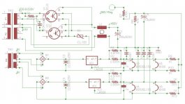
This is my idea for PSU for PP mono-block power amp having 2 6H30 tubes and 2 6550/KT88 or EL156.
HT is coming slow due to use of 2 6CJ3 tubes as rectifiers with additional CL-150 NTC Thermistor in series with the heaters voltage.
The amp tubes are being warmed slowly due to Constant Current Regulator. The current sensing resistor should be changed between 6550/KT88 and EL156, since the former heater current is 1.6A, while the later heater current is 1.9A.
Attachments
I'll be darned if I can remember. Sorry. It was long ago and in a galaxy far, far away. I do remember the heater voltages, for some strange reason. The Schoeps were old, came out of the ORTF and had their special connector. Dedicated power supplies. 50's/60s' vintage maybe...
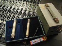
Like these?
On the left a Neumann KM254 with the German broadcast standard connector. They had to make the body of the mic bigger at the bottom to accomodate the standard connector which was used on all mics. The voltages were also standardized around the AC701 tube, such that a special U-67 was made (M269) with an AC701 instead of the EF86 tube.
They also were required to remove the Neumann logo plate due to advertizing laws forbidding "product placement" in broadcast TV. Somewhere there's a big drawer full of Neumann logos that would be worth a fortune today...
On the right is the Schoeps M221b which also uses the AC701 tube but has the standard DIN connector still available. Look closely and you'll see a Telefunken logo lightly etched into the body of the mic. That must have been OK because it's not obvious.
The AC701 tube has lead wires and is soldered in. The wire on top is for the grid, which is physically separate from the base wires because of the high impedance the grid circuit operates at. The tube spec is 50Mohms but they are used up to 200Mohms, with fixed bias. Obviously any grid leakage at all will saturate the circuit and cause all kinds of noise and distortion if there is any output at all. The AC701 is designed for very long service life under it's rated conditions.
The power supply on the right is the vintage unit made by Schoeps (or at least branded by Schoeps) for these mics. It looks a lot like a Neumann NKM. I also have some vintage modular supplies for these tubes. They have solid state rectifiers and apply plate voltege simultaneously with heater voltage...
Attachments
Last edited:
Yep, that looks a lot like it! The 2 pair of Schoeps I used where not as directional, so not all the side vents. Can't tell for sure about the connector, but it was whatever the ORTF used back in the 60's. Had to build special cables for them. Power supply looks very familiar, too. Thanks for the pix. Are you still using these?
This is my idea for PSU for PP mono-block power amp having 2 6H30 tubes and 2 6550/KT88 or EL156.
HT is coming slow due to use of 2 6CJ3 tubes as rectifiers with additional CL-150 NTC Thermistor in series with the heaters voltage.
The amp tubes are being warmed slowly due to Constant Current Regulator. The current sensing resistor should be changed between 6550/KT88 and EL156, since the former heater current is 1.6A, while the later heater current is 1.9A.
That is a power supply for really gentle treatment of valves!
only a couple of points about the schematic:
- rectifier snubber often works at 50 ohms nominal (select from 10 to 100 Ohms if you can measure the turn-OFF region of the rectifiers)
- current regulation of heaters is very kind, but regulating two in parallel may give problems with sharing. Could current-reg the two EL156 in series, and the two 6H30 in a separate series string, or separate regs for each (they're hardly expensive)
Thanks, Rod.
I'll make 3 heater regulators, 1 for each of OP tubes and one for the 2 6H30 in series. The power trafo is custom made, anyhow.
Once the amp will be built (it will take a while), I'll be able to measure with a scope the turn off region of the rectifiers. How do I calculate from it the value of the snubber resistor?
Thanks, Rod.
I'll be able to measure with a scope the turn off region of the rectifiers. How do I calculate from it the value of the snubber resistor?
It escapes calculation really, unless you know the inductance of the secondary, and the storage charge in the rectifiers.
Kurt, (Zigzagflux) is the expert here. We try to measure the very short turn-OFF current as the rectifiers go reverse-biassed. Making a current probe (a little toroidal ferrite core with a few turns on it, and a single well isolated 'primary' turn, through which the output of the rectifier flows. Measure the 'secondary', loaded with 50 ohms on a scope at 500ns or so.
Adjusting the resistor value can minimise the little bump in the tur-OFF waveform.
Your power supply is very like the design I actually use. I use a separate mains connexion for heating, which is ON a minute or two before the HT - current driven heaters take a while to reach temperature.
- Status
- Not open for further replies.
- Home
- Amplifiers
- Tubes / Valves
- Lets settle the b+ on cold tubes issue!