Variac, 10/10 for your math. If the TT is made with the complete bottom surface of the platter as a bearing, it would be even less. With a 320mm platter, you end up at about 1245 Pa for your 10 kg platter. Or about 0.5 psi. This is peanuts compared to the pressure of the ruby ball unipivot.
Bearings.
Havoc,
I think I'm starting to understand you when you said in previous post:
When using an airbearing I would use a direct drive...🙄
Sweet chocolates from B.,
Havoc,
I think I'm starting to understand you when you said in previous post:
When using an airbearing I would use a direct drive...🙄
Sweet chocolates from B.,
fdegrove,
Yes, from your first comments, it seems that you didn't realize that the 50mm ball is an air bearing. Read my original post (on one of the first pages!)and I describe how I saw this type of bearing work. LAter there are some diagrams, but they also have a flat radial bearing surface too- not necessary for a unipivot. Also, how easy it is to make a cup using the ball itself and epoxy.Cost is low too: just the cost of the precision ball, and an air pump. I attach the ball to the platter so that the epoxy cup is in the base and is easy to drill for the air supply. This places the pivot point lower than I wanted originally, but what got me back into the idea is the claim that a more central pivot is more dynamically stable. Also, as Dice points out, air bearings are very stiff although you'd think they'd be mushy. A very thin air layer helps it be stiff I think.
It appears that the lateral support area would be about half of the vertical area. BUT than still gives it enough to resist 5Kg lateral force if the pressure is for a 10 kg platter. So... I don't see any reason that the lateral load from a belt would be any problem at all.
Thanks for the grade Havoc Thats better than I usually got!
😎 cool Mark
BEARINGS
Mark,
Let it be understood:when I reply to a post I try to serve or imagine the needs of the person starting it.Deja vu??😉
And as far as air bearings go:hold your breathe,I still have some tricks up my sleeve.
Seriously?Air bearings are just as stiff as the pressure applied to them,that's plain physics to me...😎
Remember Isaac Newton?
Try to do some caligraphy on a pillow.
And I fail (stupid me) to see what a ball has to do with air bearings anyway,or what good it can do?
I already asked off line for someone willing to do some drawings on the ideas I'd wanted to put forward but had no posistive reply.No reply really.
Pedro put his help forward,for which I thank him,but there may be a linguistic barrier here making things harder then they need to.
An airbearing TT musn't be too complicated,still we're talking diy here.😉
The point being do we want to go one better compared to Mrs,Walker and such?
The only participant I know of in this thread having the skills to do that is Havoc IMHO.
I know it may not seem nice to you,still that's what I have concluded from this mile long post.
Cheers,😉
bad news: VEM motor junk
difool and peterr,
bad news with the VEM motor. See the order list in the Electronics & Parts board.
2 of the 4 motors i tried out showed malfunction: particles inside impeding a smooth running. Moreover all motors are comparatively noisy. Meanwhile i managed the 3rd motor to run as fine as it did in the shop. I suppose the whole VEM lot to be rejects; your decision whether you want them. I would rather not ship them, 5 Euro is not much but there is extra shipping then.
All,
i have one maxon motor running for 24 hours, fed by an LM317 lab supply. No speed variation observable and my TT plays beautiful music with it.
Art Ensemble of Chicago, "People in Sorrow" at the moment.
Frank,
is there a problem for you to take a paper and a pencil and sketch your ideas and scan them and post them?
Or take one of the simple shareware CADs out there and draw them? And post them? 😕
Or some pixel paint program?
I would love to see some of your ideas. 🙂
is there a problem for you to take a paper and a pencil and sketch your ideas and scan them and post them?
Or take one of the simple shareware CADs out there and draw them? And post them? 😕
Or some pixel paint program?
I would love to see some of your ideas. 🙂
Frank,
The problem here I guess is that you said that you have carefully read the thread so I assumed that you had. Dice tried to explain it to you be also noted that it was in the thread. Why don't you look at my first input on page 3 and drawings that follow by Dice and me. My first input tells how to do this simple air bearing in a unipivot configuration. The drawings show a radial bearing also, but it isn't necessary in a unipivot. The key is that first text message on p. 3
Now there may be many problems with this bearing, but it will certainly not be expensive!! It is about the cheapest approach in fact! -depending on how you get a compressor. The ball should also handle cosiderable side pressures if the correct number of nozzles are used. That is why I'm confused about your concern with that.
It may be a bad idea but I am interested in input as to why. Yes of course the pressure makes it stiffer. but some people claim higher pressures have their own problems i.e. chattering?
The other reason I brought it up again is that it is interchangable with a conventional post with ball on top and thrust plate. The current design could be made either way. Also unless the bearing is constrained as Dice Bernhard prefers, won't higher pressures just make the gap thicker and thus more springy again?
Your first posting promised lots of ideas and lectures using big words, looking foward to their arrival.
Peterr: I sure like the platter option with part of the turntable extending over the crack.
If a conventional thrust plate bearing is used, I like the idea of the resovior feeding the bearing oil, very simple, and the oilviscosity might not be that important in the bearing.
The pressure you will have to use is related to a couple of things:
- the surface of the bearing, so it makes a big diference if you only use the ball as a unipivot, or if you use the ball and the bottom of the platter
- the weight of the platter
The height of the platter will only influence how much air you need. (I will also influence the pressure, but less than the first 2 points)
Frank, check out the airbearing drawings please....
DIY TT
Mark,
Absolutely,I did wade through that,Mark.
And the whole thing is printed out and right here on my desk.
My problem was that you dropped this info related to that suggestion for an airbearing in the middle of something (in my mind at least) else.
So,you got me confused as I assumed you were commenting on Livemusic's suggestion.
So forgive me?
The problem I saw with that ball introduced (and it must be said,it is confusing when all these engineering terms get mixed where they do not relate to the subject) in an airbearing is that you are then basically trying to balance a plate on a snooker ball.
Now that is hard enough to achieve and totally unnecessary IMHO.
To make matters worse you will have a belt of some sort attached to the side that will have to spin that plate around somehow.
So,in conclusion the introduction of that ball seems to me like introducing a problem whereas a simpler solution is called for IMHO?
What I suggest you could do is combine both and use them where most appropiate.
For example:You could use a conventional airbearing (stator + rotor) and stand that upright instead of horizontally as in a tangential tonearm.
You could then put half of a ball (half hemisphere) on top of its stator and perforate it (as a showerhead) so the airpressure would give extra lift with even distribution.(Assuming both stator and rotor are hollow and air is pressurised through air inlets to the stator)
The platter would then have a mirrored half hemisphere,hollow part matching the one on the stator.
The platter here would be either attached to the rotor or simply be machined as the rotor.
The advantage of using a traditional air bearing would be that the pressure on the vertical flanges between rotor and stator would give sufficient rigidity to the sides so the effect of sidewards thrust form belt/motor pull can be neglected.
On the other hand you could do away with the half hemisphere altogether since it really serves no particular purpose other than perhaps making for a gentle landingstrip in a case of sudden loss of airpressure.
Since the lift of the platter needs only be the bare minimum so rotor and stator don't stick I don't loose sleep over that anyway.
And saying I could have done that with a drawing or two!
Havoc,
Correct,there are a number of possibillities.
Assuming you don't want a spungy interface between platter and needle tip,the higher the mass the more pressure and air volume you're going to need not just to lift the mass but more importantly IMO for rigidity.
To all:
One last minor quibble:
a unipivot is by nature for uses where you need something to pivot in both vertical and horizontal planes.
(as in a tonearm.)
When we're talking about bearing types for TT's a pivot is the last thing you want to use.
But I'm nitpicking,I guess.
Bernhard,
Think I'm going for the paper drawing/scanner solution you suggested.
I can't risk anything happening to the machines here,contracts depend on them.
I shouldn't have bugged you with that anyway.
Thanks for caring.😉
Any suggestions are welcome,
Rgds,
Mark,
The problem here I guess is that you said that you have carefully read the thread so I assumed that you had.
Absolutely,I did wade through that,Mark.
And the whole thing is printed out and right here on my desk.
My problem was that you dropped this info related to that suggestion for an airbearing in the middle of something (in my mind at least) else.
So,you got me confused as I assumed you were commenting on Livemusic's suggestion.
So forgive me?
The problem I saw with that ball introduced (and it must be said,it is confusing when all these engineering terms get mixed where they do not relate to the subject) in an airbearing is that you are then basically trying to balance a plate on a snooker ball.
Now that is hard enough to achieve and totally unnecessary IMHO.
To make matters worse you will have a belt of some sort attached to the side that will have to spin that plate around somehow.
So,in conclusion the introduction of that ball seems to me like introducing a problem whereas a simpler solution is called for IMHO?
What I suggest you could do is combine both and use them where most appropiate.
For example:You could use a conventional airbearing (stator + rotor) and stand that upright instead of horizontally as in a tangential tonearm.
You could then put half of a ball (half hemisphere) on top of its stator and perforate it (as a showerhead) so the airpressure would give extra lift with even distribution.(Assuming both stator and rotor are hollow and air is pressurised through air inlets to the stator)
The platter would then have a mirrored half hemisphere,hollow part matching the one on the stator.
The platter here would be either attached to the rotor or simply be machined as the rotor.
The advantage of using a traditional air bearing would be that the pressure on the vertical flanges between rotor and stator would give sufficient rigidity to the sides so the effect of sidewards thrust form belt/motor pull can be neglected.
On the other hand you could do away with the half hemisphere altogether since it really serves no particular purpose other than perhaps making for a gentle landingstrip in a case of sudden loss of airpressure.
Since the lift of the platter needs only be the bare minimum so rotor and stator don't stick I don't loose sleep over that anyway.
And saying I could have done that with a drawing or two!
Havoc,
The pressure you will have to use is related to a couple of things:
Correct,there are a number of possibillities.
Assuming you don't want a spungy interface between platter and needle tip,the higher the mass the more pressure and air volume you're going to need not just to lift the mass but more importantly IMO for rigidity.
To all:
One last minor quibble:
a unipivot is by nature for uses where you need something to pivot in both vertical and horizontal planes.
(as in a tonearm.)
When we're talking about bearing types for TT's a pivot is the last thing you want to use.
But I'm nitpicking,I guess.
Bernhard,
Think I'm going for the paper drawing/scanner solution you suggested.
I can't risk anything happening to the machines here,contracts depend on them.
I shouldn't have bugged you with that anyway.
Thanks for caring.😉
Any suggestions are welcome,
Rgds,
DIY TT
Guys,
Just some specs on what can you expect from an industrial airbearing:
Speeds from 0 to 180,000 rpm
Power from 10W to 30kW
Loads up to:
330 lbsf radial (150 kgf)
227 lsbf axial (103 kgf)
Bearing stiffness up to:
50kg/µm radial through bearing center line (2,800,000 lsbf/in)
50kg/µm axial (670,000 lsbf/in)
Think that summs it up nicely?
Cheers,
Fdegrove
-trying to balance a plate on a snooker ball.
-Now that is hard enough to achieve and totally unnecessary
-IMHO.
Yes, it is unnecessary, Thats why in my original post on page 3
I mention the platter must have a rim hanging below the pivot point The drawings show a different set up because they
have a huge radial air bearing. Please read the post on page 3 as I requested, then you will see that the current unipivot design is the same geometry as what I was proposing-but now has cool fluid damping-flotation. thus, my point is that the ball air bearing is interchangable with the current unipivot tha's why I mentioned it when I did.
-To make matters worse you will have a belt of some sort
-attached to the side that will have to spin that plate around
- somehow.
How is this different than the current unipivot with a small ball and a thrust plate? except that the air bearing has no grinding noise or vibrations introduced into the system? This is the essence of the current design that Peterr is working on-Use a unipivot, an idea that others haven't done because it appears to have drawbacks, and try it anyway, because Peterr thinks we have solved a lot of those limitations. On page 3 I mention a huge advantage of the huge ball air pivot-I've seen it work!
-So,in conclusion the introduction of that ball seems to me like
-introducing a problem whereas a simpler solution is called for
- IMHO?
Say..... why don't you read my first post on page 3, it describes how simple this bearing is to make
-..........On the other hand you could do away with the half
- hemisphere altogether since it really serves no particular
- purpose other than perhaps making for a gentle landingstrip in
- a case of sudden loss of airpressure.
This is called a straw man argument. You made up a long story with your suggested ideas incorporating mine , in a way that I did not suggest, then say it doesn't make sense and there is no point to it. Yes, doing it the way you suggest doesn't make sense, but that is not my proposal.
-a unipivot is by nature for uses where you need something to
- pivot in both vertical and horizontal planes.(as in a tonearm.)
Actually a unipivot is not ideal for a tone arm either-that is why they aren't used much now. Why? because they pivot in three planes, not just the two you mention. I agree that more axis then you need is generally bad. The best old ones were damped with fluid-sound familiar? With this unipivot turntable there are 2 extra axis instead of one extra in your tonearm.
-When we're talking about bearing types for TT's a pivot is the
- last thing you want to use.
Well duh!! The point here isthat it seems like a lot of these problems might be solved with things like the fluid damping,
And there might be some advantages to the unipivot. IT apears that it is very stable once up to speed, there are no side loads from sleeve bearings scraping on a shaft as in a typical ball on a stick with thrust plate and sleeve bearing configuration.
This is an experimental project- The idea has become to try a new design as see how it performs. Many naysayers has already stated that this design won't work and been proven wrong (to this point, no records played yet though!!!!!!) If you want a great turntable just take your $70,000 and get a Rockport(a Rockport is all air bearing) or some such. Or copy an existing design that you know works. We are trying something new that might not turn out to be the best, but just might turn out to have a lot of benefits. It is also about the simplest design possible for a DIY person. Contrary to your claims, we have resisted people trying to turn this into a very expensive state of the art turntable because of Pedro's original request. It is in the spirit of what he requested, and if you think about it, about the simplest turntable possible to be made DIY.
The maker of the Rockport said in an article that most people claimed low pressure is superior, but he used high pressure to pretty great effect it appears. The naysayers claim that high pressure induces turbulence. His turntable say not!!
In the August 2000 Stereophilereview of the Rockport, Andy Payor, the designer claims high pressure is the way to go, and the bearings should be captured, so they are supported in both directions of an axis. This is the feeling of our Diceman also and I'm sure he's right. The only problem is complexity. Mr. Payor also insists on the minimum number of axis to do the job so he would hate the unipivot!. But I don't think we are trying to compete on the very highest end.
Finally I see this as a project that can be built in various iterations by the builder. Big ball air pivot (constrained or not)or thrust plate/sleeve, people can build it as they like-we ain't got no turntable police to see if they do it the "right " way. I'm going to go back and review Dices captured big ball air bearing. whooyeee
Mark
-trying to balance a plate on a snooker ball.
-Now that is hard enough to achieve and totally unnecessary
-IMHO.
Yes, it is unnecessary, Thats why in my original post on page 3
I mention the platter must have a rim hanging below the pivot point The drawings show a different set up because they
have a huge radial air bearing. Please read the post on page 3 as I requested, then you will see that the current unipivot design is the same geometry as what I was proposing-but now has cool fluid damping-flotation. thus, my point is that the ball air bearing is interchangable with the current unipivot tha's why I mentioned it when I did.
-To make matters worse you will have a belt of some sort
-attached to the side that will have to spin that plate around
- somehow.
How is this different than the current unipivot with a small ball and a thrust plate? except that the air bearing has no grinding noise or vibrations introduced into the system? This is the essence of the current design that Peterr is working on-Use a unipivot, an idea that others haven't done because it appears to have drawbacks, and try it anyway, because Peterr thinks we have solved a lot of those limitations. On page 3 I mention a huge advantage of the huge ball air pivot-I've seen it work!
-So,in conclusion the introduction of that ball seems to me like
-introducing a problem whereas a simpler solution is called for
- IMHO?
Say..... why don't you read my first post on page 3, it describes how simple this bearing is to make
-..........On the other hand you could do away with the half
- hemisphere altogether since it really serves no particular
- purpose other than perhaps making for a gentle landingstrip in
- a case of sudden loss of airpressure.
This is called a straw man argument. You made up a long story with your suggested ideas incorporating mine , in a way that I did not suggest, then say it doesn't make sense and there is no point to it. Yes, doing it the way you suggest doesn't make sense, but that is not my proposal.
-a unipivot is by nature for uses where you need something to
- pivot in both vertical and horizontal planes.(as in a tonearm.)
Actually a unipivot is not ideal for a tone arm either-that is why they aren't used much now. Why? because they pivot in three planes, not just the two you mention. I agree that more axis then you need is generally bad. The best old ones were damped with fluid-sound familiar? With this unipivot turntable there are 2 extra axis instead of one extra in your tonearm.
-When we're talking about bearing types for TT's a pivot is the
- last thing you want to use.
Well duh!! The point here isthat it seems like a lot of these problems might be solved with things like the fluid damping,
And there might be some advantages to the unipivot. IT apears that it is very stable once up to speed, there are no side loads from sleeve bearings scraping on a shaft as in a typical ball on a stick with thrust plate and sleeve bearing configuration.
This is an experimental project- The idea has become to try a new design as see how it performs. Many naysayers has already stated that this design won't work and been proven wrong (to this point, no records played yet though!!!!!!) If you want a great turntable just take your $70,000 and get a Rockport(a Rockport is all air bearing) or some such. Or copy an existing design that you know works. We are trying something new that might not turn out to be the best, but just might turn out to have a lot of benefits. It is also about the simplest design possible for a DIY person. Contrary to your claims, we have resisted people trying to turn this into a very expensive state of the art turntable because of Pedro's original request. It is in the spirit of what he requested, and if you think about it, about the simplest turntable possible to be made DIY.
The maker of the Rockport said in an article that most people claimed low pressure is superior, but he used high pressure to pretty great effect it appears. The naysayers claim that high pressure induces turbulence. His turntable say not!!
In the August 2000 Stereophilereview of the Rockport, Andy Payor, the designer claims high pressure is the way to go, and the bearings should be captured, so they are supported in both directions of an axis. This is the feeling of our Diceman also and I'm sure he's right. The only problem is complexity. Mr. Payor also insists on the minimum number of axis to do the job so he would hate the unipivot!. But I don't think we are trying to compete on the very highest end.
Finally
I see this as a project that can be built in various iterations by the builder. Big ball air pivot (constrained or not)or thrust plate/sleeve, people can build it as they like-we ain't got no turntable police to see if they do it the "right " way. I'm going to go back and review Dices captured big ball air bearing. whooyeeeMark
Dice, Fdegrove
Ball bearing chatter caused mainly by retainer/separator sliding on balls surface, IMHO. Area of contact is very substantial, and relatively light separator is realy shaking. For deep groove bearing, the ball-groove multiply contacts also contribute.
7 ball tetra bearing has very small area af contact: 6 points by 0.11 sq. mm each for 16 kg platter and 10 mm balls (calculations, again) and perfectly even load distribution. I have no test substantiations, but something make me think that good quality alloy steel balls, used for heavy loaded machinery (like turbo-jet engines, myself is dealing with), can easily slide one on the other in lubicating oil enviroment wihtout causing any vibrations due to micro-sticking, beacause the load is way lower the ball bearing is designed for. The ideal choice would be the central ceramic ball, virtually eliminating micro sticking/welding between ceramic and steel (read any net article about ceramic bearings).
Generally, we have two choises: one unipivot bearing with hydro/air/gyro stabilization or two bearings – one journal (plain) and one thrust bearing (ball), no need for additional platter stabilization, but bearing-related problems are also doubled. The bearing is the main challenge for DIY-er, and it is very attractive to make use of the perfectly precise thing, may be obtained at virtually no cost, like bearing balls.
Variac
The sphere air bearing efficiency is about 0.3, so your air pressure should be multiplied by 3, if you are using the only ball air bearing. Actually for 5 cm ball and 10 kg platter we are speaking about 40 – 50 psi air souce. Of cource, if the lower platter surface used for air cushion, the pressure required is way lower, but the air flow is much more substantial (see the pump pressure/flow characteristics)- "no free lanches in physics". Moreover, the small air gap, which is essential for for the rigid air bearing, needless to say, is the challenge by itself, and it is hard to imagine how can one adjust exactly he same gap for the plane and spherical part of the bearing.
If you read about new Kuzma air tracker tonearm in Audio Asylum (really nice stuff for 6000 USD), they claim the quietest pump available (50 psi) is used and it is still recommended to place it in the separate room! I use the pretty quiet aquarium pump for my DIY linear air tracker, and it is surprisingly audible during midnight listening session using earphones. This keep me still away from air bearing, besides expences–related apprehensions.
Regards
Michael
DIY TT
Folks,
Mark:I reread pages 2 through five this afternoon for the umpteenth time.
If
a) you agree it is unnessary in the first place then why hang on to it?
b)before you accuse others of not understanding your point ,(which I, amongst others, do) please make the same effort as we do and maybe I should have the audacity to point you to Dice's objections and mine.If you think you don't need our help then that's fine by me.
Go ahead without our blessing.
c)Don't compare apples to pears:your bearing is an air-bearing so don't compare it to a ball and thrust bearing.Their behaviour is not the same although you manage to introduce the same shortcomings of this type of bearing.
d)If you wanted to build your system as you propose it,it would have made clear to you,blatantly so,what your design shortcomings are.
e)If you read through my posts (even if I write in a provocative manner) you should understand by now I never endorsed Peterr's design either.If he's happy with it however I'm happy for him.Period.
And why should that not apply to you either?
Do I have to apply reverse psychology here before it dawns on you??🙁
Yes it is different as I explained already many times over and over.You don't have any braking force you can introduce to control any sideways thrust.In a conventional ball and thrust bearing you can still introduce a means of counteracting this.
Yes,in an ideal world the only friction left is shear friction.Which is exactly the cause of your problem.
No,you've seen it wobble.Unless you need multiplanar liberty of movement don't do this here please.
Er,do you actually read my posts???
Well,again, make it.You will soon find out how "simple" it really is.
Really?I don't see any resemblance.But if that were to be the case you would be arguing against your own ideas anyway.
No,the reason is that it is easier to design a multiple bearing one.
Less I need to go back to the textbooks:the worlds best tonearms are uni-pivots.
And that's not to say that all uni pivots are better than more conventional multi-bearings.
And we don't want to start a thread on that here now,do we?
Also they should move in no more than TWO planes not THREE and precisely THAT is the challenge.
Sure,why go through all this trouble and then camouflage all design flaws by damping them.
Sounds like the "brush and carpet" technique to me.
You should also consider what damping does to the sound of the TT.
Sure,if and when executed correctly.You'll never hear me dismiss off hand a well executed conventional bearing.Hell,I've been defending the thing from the day I was silly enough to participate in this project.
I don't know, but weren't you dismissing uni-pivots just a minute ago?
Anyway,if you decide to go for the single bearing point approach, you have to take preload of your bearing into account.In this case in particular:the higher the preload on your bearing the more it will be impervious to sideways pull from the motor/pulley assembly.All else executed correctly of course.
And yes I suggested solutions for that too.
But I think you never did make it past page three.
Have you really tried to imagine how that is going to affect your design proposition?
Not to mention the fact you won't be able to resort to band-aids such as oil damping in your design.
Admittedly I would like for you to give that a try...
I don't have a problem with that as long as it is your money that's on the line.
Excuse me?Have I missed out on something?
By all means try.
Can't be that new since you claim to have "seen it work" elsewhere?
And yes I will tell you "I told you so" after you fall flat on your face.
Is that important to you?
Ah,that's something else entirely.This proves again you really haven't dragged yourself through the pages beyond number 3.
Which is no small feat,I admit.
In case you wonder about expenses:usually in life what you get is what you pay for.Except for diy.I reckon??
And no, 70K is a bit outside my league.But if we can do it for 5K I think that's realistic for a prototype.And it would be a major success.
You wouldn't have noticed but there are several people designing for a budget here already and some are halfway through finishing what they aspired to.
For myself and some other participants I want to at least have the liberty to design a no holds barred concept.If someone actually wants to build a proto for that then they sure have my blessing and I for one can be proud to have contributed to it.
I agree,high mass high pressure.
Turbulence is created when you don't consider aerodynamics IMHO.But that is again a compromise where you need to balance things.
But what is your point,you're contradicting yourself again?
Er,single ball bearing is the minimal number of axis so it just goes to show you're contradicting yourself again.
What I resent with most tangential air bearing tonearms is a lack of mass and rigidity in the designs.Sonically that will rub your system of it's bass.Which to my mind is where all music has it's foundations.
And frankly, I don't give a rats *** about what the press has to say about this.
What I have proposed so far is utterly simple,I would think?
Never saw so much contradictions in so little words but yes, I do see your point.
Still ,do read the posts and you wil notice you're barking up the wrong tree.
Rgds,😉
Folks,
Yes, it is unnecessary, Thats why in my original post on page 3
Mark:I reread pages 2 through five this afternoon for the umpteenth time.
If
a) you agree it is unnessary in the first place then why hang on to it?
b)before you accuse others of not understanding your point ,(which I, amongst others, do) please make the same effort as we do and maybe I should have the audacity to point you to Dice's objections and mine.If you think you don't need our help then that's fine by me.
Go ahead without our blessing.
c)Don't compare apples to pears:your bearing is an air-bearing so don't compare it to a ball and thrust bearing.Their behaviour is not the same although you manage to introduce the same shortcomings of this type of bearing.
d)If you wanted to build your system as you propose it,it would have made clear to you,blatantly so,what your design shortcomings are.
e)If you read through my posts (even if I write in a provocative manner) you should understand by now I never endorsed Peterr's design either.If he's happy with it however I'm happy for him.Period.
And why should that not apply to you either?
Do I have to apply reverse psychology here before it dawns on you??🙁
How is this different than the current unipivot with a small ball and a thrust plate?
Yes it is different as I explained already many times over and over.You don't have any braking force you can introduce to control any sideways thrust.In a conventional ball and thrust bearing you can still introduce a means of counteracting this.
or vibrations introduced
Yes,in an ideal world the only friction left is shear friction.Which is exactly the cause of your problem.
I've seen it work!
No,you've seen it wobble.Unless you need multiplanar liberty of movement don't do this here please.
Er,do you actually read my posts???
Say..... why don't you read my first post on page 3, it describes how simple this bearing is to make
Well,again, make it.You will soon find out how "simple" it really is.
You made up a long story with your suggested ideas incorporating mine
Really?I don't see any resemblance.But if that were to be the case you would be arguing against your own ideas anyway.
Actually a unipivot is not ideal for a tone arm either-that is why they aren't used much now.
No,the reason is that it is easier to design a multiple bearing one.
Less I need to go back to the textbooks:the worlds best tonearms are uni-pivots.
And that's not to say that all uni pivots are better than more conventional multi-bearings.
And we don't want to start a thread on that here now,do we?
Also they should move in no more than TWO planes not THREE and precisely THAT is the challenge.
Well duh!! The point here isthat it seems like a lot of these problems might be solved with things like the fluid damping,
Sure,why go through all this trouble and then camouflage all design flaws by damping them.
Sounds like the "brush and carpet" technique to me.
You should also consider what damping does to the sound of the TT.
And there might be some advantages to the unipivot. IT apears that it is very stable once up to speed, there are no side loads from sleeve bearings scraping on a shaft as in a typical ball on a stick with thrust plate and sleeve bearing configuration.
Sure,if and when executed correctly.You'll never hear me dismiss off hand a well executed conventional bearing.Hell,I've been defending the thing from the day I was silly enough to participate in this project.
I don't know, but weren't you dismissing uni-pivots just a minute ago?
Anyway,if you decide to go for the single bearing point approach, you have to take preload of your bearing into account.In this case in particular:the higher the preload on your bearing the more it will be impervious to sideways pull from the motor/pulley assembly.All else executed correctly of course.
And yes I suggested solutions for that too.
But I think you never did make it past page three.
Have you really tried to imagine how that is going to affect your design proposition?
Not to mention the fact you won't be able to resort to band-aids such as oil damping in your design.
Admittedly I would like for you to give that a try...
This is an experimental project
I don't have a problem with that as long as it is your money that's on the line.
stated that this design won't work and been proven wrong
Excuse me?Have I missed out on something?
We are trying something new that might not turn out to be the best, but just might turn out to have a lot of benefits. It is also about the simplest design possible
By all means try.
Can't be that new since you claim to have "seen it work" elsewhere?
And yes I will tell you "I told you so" after you fall flat on your face.
Is that important to you?
It is also about the simplest design possible for a DIY person. Contrary to your claims, we have resisted people trying to turn this into a very expensive state of the art turntable because of Pedro's original request. It is in the spirit of what he requested, and if you think about it, about the simplest turntable possible to be made DIY.
Ah,that's something else entirely.This proves again you really haven't dragged yourself through the pages beyond number 3.
Which is no small feat,I admit.
In case you wonder about expenses:usually in life what you get is what you pay for.Except for diy.I reckon??
And no, 70K is a bit outside my league.But if we can do it for 5K I think that's realistic for a prototype.And it would be a major success.
You wouldn't have noticed but there are several people designing for a budget here already and some are halfway through finishing what they aspired to.
For myself and some other participants I want to at least have the liberty to design a no holds barred concept.If someone actually wants to build a proto for that then they sure have my blessing and I for one can be proud to have contributed to it.
The maker of the Rockport said in an article that most people claimed low pressure is superior, but he used high pressure to pretty great effect it appears. The naysayers claim that high pressure induces turbulence. His turntable say not!!
I agree,high mass high pressure.
Turbulence is created when you don't consider aerodynamics IMHO.But that is again a compromise where you need to balance things.
But what is your point,you're contradicting yourself again?
This is the feeling of our Diceman also and I'm sure he's right. The only problem is complexity. Mr. Payor also insists on the minimum number of axis to do the job so he would hate the unipivot!. But I don't think we are trying to compete on the very highest end.
Er,single ball bearing is the minimal number of axis so it just goes to show you're contradicting yourself again.
What I resent with most tangential air bearing tonearms is a lack of mass and rigidity in the designs.Sonically that will rub your system of it's bass.Which to my mind is where all music has it's foundations.
And frankly, I don't give a rats *** about what the press has to say about this.
The only problem is complexity
What I have proposed so far is utterly simple,I would think?
Big ball air pivot (constrained or not
Never saw so much contradictions in so little words but yes, I do see your point.
Still ,do read the posts and you wil notice you're barking up the wrong tree.
Rgds,😉
DIY TT
Michael,
If you have a conventional ball bearing in mind,yes.
Check page 3 again for what Bernhard said about the bearing he has currently in his system.
I don't see any need for concern here:imagine a half hemisphere sitting (better fixed) on a bearing rod.That will then rest in an inverted cup made naturally bu the softness of the teflon thrustplate.
If you know now that tefon has about the same friction as ice and it's natural "softness" captures the ball for 1/4 of its height than why make it so complicated by using "tetra bearings"?
I must admit your design has me puzzled.
Re: air bearings:modern jet engines use slider type air bearings not old fashioned ball bearings.
And all pressure needed can be easily calculated.
Pls,see my previous post .😉
Michael,
Ball bearing chatter caused mainly by retainer/separator sliding on balls surface, IMHO
If you have a conventional ball bearing in mind,yes.
Check page 3 again for what Bernhard said about the bearing he has currently in his system.
I don't see any need for concern here:imagine a half hemisphere sitting (better fixed) on a bearing rod.That will then rest in an inverted cup made naturally bu the softness of the teflon thrustplate.
If you know now that tefon has about the same friction as ice and it's natural "softness" captures the ball for 1/4 of its height than why make it so complicated by using "tetra bearings"?
I must admit your design has me puzzled.
Re: air bearings:modern jet engines use slider type air bearings not old fashioned ball bearings.
And all pressure needed can be easily calculated.
Pls,see my previous post .😉
Frank,
Can you call the ball-teflon plate bearing described by Bernhard “stiff”? The Teres group abandoned delrin (much harder material than Teflon) thrust plate in favor of steel one, as far as I know from similar reasons. How can one prevent the ball from slow drift upon Teflon plate surface, under side load (belt tension, tiny platter unbalance) or even without it? No exact centering, good-by precise tonearm overhang – not high-end league, IMHO. Those are the simple reasons behind my tetra-bearing proposal, not a puzzle at all.
The other Bernhard’s proposal I remember was the ball supported by shallow cone. Compare to this, the tetra bearing has smaller and much more predictable contact area.
I'm not trying to promote my own design, not at all, and I can change my mind in a minute, but I'd like to hear argumented objectins.
Re: Glad to hear you are familiar with the last researches in the jet engines bearings area, but the conventional type bearing is still good enough to be appreciated by DIY-ers.
Yours truly,
Michael
DIY TT
Michael,
No,I wouldn't call that stiff.It is however a compromise I consider better then others I've seen.
If you care to eleborate?We try to keep an open mind,any input is welcomed.
But in my opininion your suggested bearing does exactly the same thing,only the roles are reversed.Your cup is formed by the balls beneath and the upper ball is riding their circumference whereas the other has the circumference of the lower ball riding the teflon.
This is,provideded your lower ball assembly is really press-fit.If it isn't it would only make matters worse.
I am by no means an experts on this.
Please,explain in a more detailed manner your thinking behind the "tetra" bearing.
Nobody is dismissing it in the first place but I fail to understand its benefits.
Sincerley,🙂
Michael,
Can you call the ball-teflon plate bearing described by Bernhard “stiff”?
No,I wouldn't call that stiff.It is however a compromise I consider better then others I've seen.
Sorry Michael,but I fail to see in what way your proposed bearing design is going to solve this problem?Those are the simple reasons behind my tetra-bearing proposal, not a puzzle at all.
If you care to eleborate?We try to keep an open mind,any input is welcomed.
But in my opininion your suggested bearing does exactly the same thing,only the roles are reversed.Your cup is formed by the balls beneath and the upper ball is riding their circumference whereas the other has the circumference of the lower ball riding the teflon.
This is,provideded your lower ball assembly is really press-fit.If it isn't it would only make matters worse.
Re: Glad to hear you are familiar with the last researches in the jet engines bearings area, but the conventional type bearing is still good enough to be appreciated by DIY-ers.
I am by no means an experts on this.
Please,explain in a more detailed manner your thinking behind the "tetra" bearing.
Nobody is dismissing it in the first place but I fail to understand its benefits.
Sincerley,🙂
Well Frank, I guess it comes down to the drawing.
If the design is brilliant enough then it was worth it to put up with your inmaturity, inability to participate in a dialogue, unwillingness (inability) to explain your ideas, and generally obnoxious attitude. I suspect some on this thread are thinking we will never see it. All we get are excuses.
P.S. "My dog ate it" won't work. 🙂
Frank,
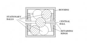
Here is the tetra-bearing description. It comprises of 6 stationary balls, each 3 of them are hold firmly together by the conical retaining ring, threaded into the bearing housing. The upper housing is connected to the platter, the lower one to TT base. The central free ball is supported by stationary balls in 6 points of contact. All the assembly is fully submerged in oil. Hence the central ball is constrained in 3 degrees of linear movement, and allowed for 3-dimentional rotations. The bearing load (platter weight) is evenly distributed by 6 points of contact, about 0.1 sq. mm area each one only (speaking about 10 mm balls and 16 kg platter). I see no reason for bearing chattering, while the central ball, having smooth surface and very tight tolerances for roundness, is sliding on the stationary balls in lubricant environment.
The bearing load is relatively small (maximum normal stress in the point of contact is about 320 kg per sq. mm), should be practically no wear. To make things even better, use the ruby or ceramic ball for the central ball. Zero backlash, very stiff, minimum machining, low cost.
Again, I will be the first to bury this design when I hear substantiated objections.
Michael
Attachments
Livemusic,
I have been reading your latest plans with great interest.😎
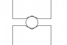
But What I don't understand is WHY you want to use your bearing construction😕 😕 What in your mind will 13 balls do better then just one (centered)? I am afraid that all I can see is more complexety and more precision manufacturing needed.
See below.
I have been reading your latest plans with great interest.😎
But What I don't understand is WHY you want to use your bearing construction😕 😕 What in your mind will 13 balls do better then just one (centered)? I am afraid that all I can see is more complexety and more precision manufacturing needed.
See below.
Attachments
DIY TT
Michael,
Thank you for the lovely drawing.
This type of bearing was used in tonearms where you need movement in two planes:
The horizontal:to allow freedom of movement accross the record.
The vertical :to allow for tracking warps in the record , otherwise
the cantilever of the cardridge would have to cater for that.
Actually the tonearm bearings used a conical pin on a thrust pad where the balls kept it horizontally and stationary in that plane.
It also acquired the reputation of being noisy.
I must add that most of them were not smeared at all since that impeded freedom of movement even more.
As you can well imagine:too much pressure actually locked the bearing,too little and these little balls were getting noisy smearing the signal along with their noise.
In a TT however you only need to allow for movement in one plane:the platter has to spin around it's own axis.
If you don't the platter will try to find its equilibrium continuously and a stable stereo image is definitely out of the window.
Now if you would tilt your drawing 180 degrees so it would lie in the horizontal plane and you were to replace the central ball by a rod you would effectively have a ball in race bearing.
The central ball= rod
The race=the balls surrounding it.
The people at Well Tempered Labs have gone through great length to avoid this source of noise.
What you want to design for IMHO is to disperse the source of noise along the stem of the central axis.
This I think, they achieved in a clever way avoiding possible tilt by the pull of the belt.
Like most other designs it is a compromise since they didn't want to use high mass to counteract this tendency.
(High mass equating high shipping costs.)
Introducing high gyroscopic effect by putting the mass mostly on the outer rim will help stabilize it but that only works provided everything is perfectly level (horizontally).
I would use it with caution.
Also,I think it was Bernhard who warned against it somewhere in the earlier pages of this thread.
But I digress.
The smaller the area of contact between the moving parts the less the risk of introducing noise.
In the case of your bearing you'ld effectively have a two line contact once the platter is spinning.
The higher the rotational speed the more noise levels are going to rise both in level and frequency.
In your design the lubricant will be retained in the lower part of the bearing assembly and will be self smearing as long as the central ball can touch it.
I don't foresee much of a problem in that area.
If you're absolutely hellbound on using this type of bearing I would seat it at the plinth (bottom) making it wider than its height with a cylindrical platter (being higher than it's diameter) having the majority of its mass at the bottom for added stability, so any chatter developed in the bearing housing sees a long path and high resistance towards the top of the platter.
Damping the housing of such a bearing with highly absorbant materials would also help.
But do not use too much of a compliant material in the vertical plane since that would effectively put the platter on a spring.
I leave you to draw your conclusions.😎
Hope this was helpful,😉
- Status
- Not open for further replies.
- Home
- Source & Line
- Analogue Source
- Let's make a DIYAUDIO TT