😀That new avatar is wild. On 1st glance it looks like something from Alien the movie. A closer look it looks like someone's supper. On 3rd look i'm back with Aliens.
 I Loooove a nice paella....
Peterr,
to your drawings:
Do you have any ideas how to keep the bearing ball / trustplate interface wetted by oil? I would recommend this.
All,
would you please check the maxon order list in the Electronics and Parts board if the quantities noted there are ok.
Then,
What do you all think of my pulley ideas described there? I have a kit with two differnt pulleys and 2 or 3 different collet chucks in mind: i do want to keep the pulley short in order to avoid excessive bearing load on the motor shaft bearing; so a stacked pulley i not a good idea.
Further, a unipivot platter needs a defined belt location vertically. So a flat belt seeking its own height position also is not a good idea. Manfred Huber has told me that to his observation, the flat belt bounces against the edges of the pulley goove on start and stabilizes its position not before a certain speed is reached. So the flat belt seeking its position could excite the platter to wobble.
The collet chuch clamping ensures that the pulley can be mounted and unmounted without force. Nevertheless the concentric running properties are always better than the motor shaft ones.
So should the motor be worn-up one day, the pulley can be recycled fo another motor.
TT
Yes,I was thinking the same thing when I saw the drawing.
The bearing should be lowered to meet the oil level,right?🙂
Rgds,
Yes,I was thinking the same thing when I saw the drawing.
The bearing should be lowered to meet the oil level,right?🙂
Rgds,
Frank,
no, the oil level should be rised. Didn't we agree the pivot point should be as close to the CoG as possible? Then, presumed the pivot is at the right location, it should stay there.
Peterr,
even if the oil is not needed to stabilize the platter, it is needed to wetten the bearing. Have the oil rise as high as possible without over flowing and polluting the record or platter top surface.
TT
Fellows,
You're right.I must have been half a sleep.
I don't know if it is the case here but all the inverted bearing I saw were self-smearing types.
They had some small cavities in the sleeve that brought the oil up once running.
Peter,hope you thought of that?
No oil,no joy.
😀
Rgds,
Fellows,
You're right.I must have been half a sleep.
I don't know if it is the case here but all the inverted bearing I saw were self-smearing types.
They had some small cavities in the sleeve that brought the oil up once running.
Peter,hope you thought of that?
No oil,no joy.
😀
Rgds,
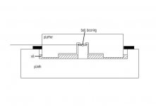
Hi all, what about this idea? Reduced drag, reduced load on the ball bearing. A tiny hole from the ball recess down into the oil should bring oil up (capilary efect).🙂
Just a thought, excuse me if you've already been there
Just a thought, excuse me if you've already been there
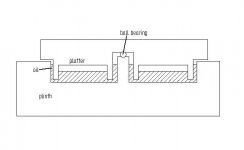
previous drawings were only meant to show possible solutions for the mess problem.  To do so I reused an older drawing.
To make sure the ball is in oil I did as below. If you look back at the 3d drawings of the prototype you can see it as well.
The advantadge is that you can use different oil types for bearing and damping.
Note that this pic is not to scale it only shows the principle.
To do so I reused an older drawing.To make sure the ball is in oil I did as below. If you look back at the 3d drawings of the prototype you can see it as well.
The advantadge is that you can use different oil types for bearing and damping.
Note that this pic is not to scale it only shows the principle.
Attachments

I guess that platter config is better that he previous one, since there is less material in the center, witch can reduce the weigth a bit and still have allmost the same inertia moment.
I would suggest some kind of hole in the center to equalize the air preasure in the mid section.
I guess there is no problem with a bit of air pressure, but the oil level will be different in both sides ( inner and outer)
I would suggest some kind of hole in the center to equalize the air preasure in the mid section.
I guess there is no problem with a bit of air pressure, but the oil level will be different in both sides ( inner and outer)

PedroPO said:I guess that platter config is better that he previous one, since there is less material in the center, witch can reduce the weigth a bit and still have allmost the same inertia moment.
I would suggest some kind of hole in the center to equalize the air preasure in the mid section.
I guess there is no problem with a bit of air pressure, but the oil level will be different in both sides ( inner and outer)
I have made a small hole in the center

Peterr,
i like your drawing, this make sense to me.
Now you can use different oils for damping the platter and lubricating the bearing.
i like your drawing, this make sense to me.
Now you can use different oils for damping the platter and lubricating the bearing.
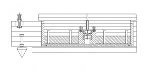
Meet the last issue of my floating – unipivot design interpretation; I’d call it “HYDRAULIC PREFERENCE”.
The main features:
1. Seven balls (double tertra pack) bearing, fully submerged in oil. Three 10 mm hardened steel balls on each side of the main one are hold by the conic retain ring, threaded in the bearing housing. Advantages:
· Zero backlash – perfectly stiff.
· Point contact ensures even load distribution on the main ball surface.
· El cheapo DIY solution (compare to air bearing).
2. The 16.5 kg platter concist of 7 layers 1 cm acrylic laminated top bolted on 1” steel bottom disc. What for? Center of mass concides with the pivot point (may be slightly below) and the center of buoyancy is a bit above it. Advantages:
· No wobbling - the platter as a gyroscope immediatelly comes to equilibrum, even at the low speed. Stability is provided by buoyant force (3.7 kg) and there is no precession due to pivot/CG shift.
· Perfect platter dumping
3. ½” VCR tape belt placed symmetrically relative to the platter rim with the idler pulley, balancing the side force and providing additional stabilization. Advantages:
· Two pulley with slightly convex surface ensure the belt stability, not allowing the belt “to climb” on larger diameter.
· Wide belt – better contact with the platter, neded to owercome the viscous friction.
· Wide belt is stiffer.
Drawback: The idler pulley is actually another source of vibrations – may be addressed by the lead insert, decoupling the pulley from TT base.
4. TT base is glued of 6 MDF layers with the circle cut-out made with a router. Additional layer(s) of lead may be added between MDF sheets for better dumping. Small balls are embedded in the bottom surface to absorb accident platter contact.
Fellows, I just recommend to make some preliminary calculations before you propose your new design (for those with engineering background) – suppose your platter tilts from any reason, and evaluate the forces and moments change result: is it in favor of stabilization or not. Above mentioned design solution is purely result of calculations (basic knowledge of gyro/hydrostatic theory honestly).
Anyone interested in details is welcomed.
Michael
Attachments
lifemusic,
very interesting, looks good!
One thing, my neck's hairs are standing stiff upright as far as your ball bearing is concerned. I would expect a lot of bearing-caused rumble. Why not go with a ruby ball and teflon friction bearing? This will easily carry your platter and run super-smooth. You will need a tunred part to keep the ruby bearing ball exactly centered and a flat trust plate made from POM or Teflon which can be easily exchcnges if worn, just,TME the trustplate will never be worn.
DIY TT
Guys,
I agree,even if the upper and lower balls were to be press fit, their contact area with the center ball is still large enough to create some serious chatter?
Just my 2 cents worth:have one ball ,say half of it,embedded and rely on the smearing to reduce any friction left (which would be minimal anyway)
A ball to flat surface contact area being a single point (static condition).
This would mimic a uni-pivot and the side thrust from the motor/puley assembly should well be counteracted by the gyroscopic effect your design offers?
Even that can be counteracted in a simple manner;introduce say a semi circular o-ring and your're done?🙄
Greetz,😉
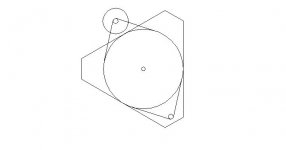
If the 50mm single ball air unipivot with epoxy socket would be supporting- let's say 10Kg. platter. The area of the ball supporting the platter weight would be:
25 squared time pi = 1964 sq mm
So the loading would be 5g. per sq. mm?
I'm thinking in mm these days so I could be off!! So, is this a high loading? What would the air pressure required be?
I guess about 7 to 10 psf?
25 squared time pi = 1964 sq mm
So the loading would be 5g. per sq. mm?
I'm thinking in mm these days so I could be off!! So, is this a high loading? What would the air pressure required be?
I guess about 7 to 10 psf?

- Status
- Not open for further replies.
- Home
- Source & Line
- Analogue Source
- Let's make a DIYAUDIO TT