All,
trying to catch up with you. Short of time, sorry for the maybe stern wording now and then, no bad vibrations intended 🙂
----------------
peted:
1) the belt always crawls on the biggest diameter within its reach. With force.
2) it the platter starts to rotate tilted, it probably remains tilted, due to being a gyro.
I agree that the oil bath will have a slight tendency to horizonalize the platter.
Forgetabout wood mockup, wood swims in oil, metal does not. Answer will be not significant, will fool you.
Oil damping platter vibrations: seconded.
Coupling disc2platter: from own experience i would not recommend liquid coupling. It sucks the life out of the music. I do recommend applying vacuum to press the record slightly on the platter. If then the platter is made from PVC and the record too, we have perfect mechanical impedance matching and the record can get rid of partial oscillation to a high percentage.
What also works fine: a thin mat made from leather, from chamois.
Careful platter design: there is no escape from it IMO. I would go as far as to say: avoid glass. Even if suited for air bearing.
The air bearing has high stffness and damping if done properly, i would expect it as effective as an oil bath. My objection against an platter air bearing: it needs considerable amounts of pressurized air. To ge such in a silent and smoothed way: expensive.
---------------------
peterr:
agreed with your unipivot bearing,worth a try. But you still have to horizontalize the platter.
I do not intend to intimidate you but the tonearm i am designing currently as well as the tonearm you see on my web site has a linear dial gauge to measure vertical tracking angle. This dial gauge resolves 0.01mm for the current one and 0.001mm for the one on my website. I am well knowing why i have this precision provided, VTA can be adjusted to 10 arcseconds precision on a pivoted arm by ear reproducably. I bet a bottle of 25ys old Scotch single malt whisky on that.
I hope that Thom Mackris from redpoint audio is right with linear trackers being not so sensitive. But neverhteless it is vital for the tonearm VTA that the platter does not change its orientation or chooses an arbitrary one on each spin-up.
Thin oil film: would help you with the said above and, no, no problem to help the platter spin-up by hand if the motor can keep speed then.
----------------------
Mark,
the mercury-floating platter TT has been built. i have seen pixes of it on the web.
THey use silicone oil to prevent the mercury from evaporating.
I have descibed my concerns with tilted platter above but if one of you comes up with a way to horizontalize the platter, methinks the unipivot platter is worth to be tried out. Use POM as trustplate, a ruby ball because it is sooo smooth, have a heavy platter. Try it. I am curious. Try it. 🙂
Flywheel: do not let the flywheel have a fat rim! Booinggg!
------------------------
peted:
use oil as bath! encouraged!
lubing the bearing ball/trustplate: essential!
airbearing: albeit the air gap is springy, it applies a constant load to the whole bearing surface, suppressing partial oscillations by that. It simply impedes 3D oscillations by its stiffness.
platter damping: platters damped dead are good as partial oscillations decay fastest.
butthen the record still has partial oscillations, atleast in close proximity to the stylus. How to get rid of them?
If the platter acts as a sink for those oscillations and can move them (or a high percentage, a high spatial angle portion of them) away from the stylus location and not have themreflected back from the record's bottom surface, then the proximity of the stylus is calm. So is the sound. Calm and transparent.
How can the platter do this service to the record? One thing is clear the oscillations must not get reflected at the record/platter interface, they have to transgress that border. The record has a mechanical impedance (complex resistance) for partial oscillations wandering along, so has the platter. Maxwell found out the reflections at an interface are minmized if impedance of both sides of the interface is the same. Maxwell's equations show this.
So if the platter is made from the same material as the record, it has same mechanical impedance. If the platter is big, oscillations can wander along in it and decay and only a very small spatial angel of them (if any) are reflected back to platter surface.
This is why i design my platters not bebe dampened dead but impedance-matched to the record.
If i would see this really fanatically, i would claim a shellac platter for shellac records.
-------------------
peted:
i would not bee alltoo afraid of turbulences in the oil. Differntial speeds are way below causing turbulence, i would guess.
-------------------
Mark,
yes, seconded, tryout everyone!
our ideas are too far apart to arrive at a design commonly agreed on. Besides that, noone bothered to contribute to a spec. I started one in the wiki, no further entry so far.
So let's toy around and share ideas and let anyone benefit and get inspired from the other's ideas and knowledge.
-------------------
peterr,
your drawings look AutoCADdish! you too ?
(hoping i catch up someday with promised LISP routines)
One thing, the platter's center plug: have it made from Delrin/POM. POM is almost as slippery as Teflon. But it keeps its form, it is dimension-stable.
And, give the plug two tiny tapped holes which can be closed by screws. One for applying oil, the other one for letting air escape.
---------------------
So, now i think i have caught up 🙂
Have a nice weekend and keep the ideas flowing!
trying to catch up with you. Short of time, sorry for the maybe stern wording now and then, no bad vibrations intended 🙂
----------------
peted:
Don't use concave surfaces for the belt to run on... a =slightly= concave belt 'groove' to make the platter naturally self levelling but important also to neutralise any tendancy to tilt by driving at the correct level.
1) the belt always crawls on the biggest diameter within its reach. With force.
2) it the platter starts to rotate tilted, it probably remains tilted, due to being a gyro.
I agree that the oil bath will have a slight tendency to horizonalize the platter.
Forgetabout wood mockup, wood swims in oil, metal does not. Answer will be not significant, will fool you.
Oil damping platter vibrations: seconded.
Coupling disc2platter: from own experience i would not recommend liquid coupling. It sucks the life out of the music. I do recommend applying vacuum to press the record slightly on the platter. If then the platter is made from PVC and the record too, we have perfect mechanical impedance matching and the record can get rid of partial oscillation to a high percentage.
What also works fine: a thin mat made from leather, from chamois.
Careful platter design: there is no escape from it IMO. I would go as far as to say: avoid glass. Even if suited for air bearing.
The air bearing has high stffness and damping if done properly, i would expect it as effective as an oil bath. My objection against an platter air bearing: it needs considerable amounts of pressurized air. To ge such in a silent and smoothed way: expensive.
---------------------
peterr:
agreed with your unipivot bearing,worth a try. But you still have to horizontalize the platter.
I do not intend to intimidate you but the tonearm i am designing currently as well as the tonearm you see on my web site has a linear dial gauge to measure vertical tracking angle. This dial gauge resolves 0.01mm for the current one and 0.001mm for the one on my website. I am well knowing why i have this precision provided, VTA can be adjusted to 10 arcseconds precision on a pivoted arm by ear reproducably. I bet a bottle of 25ys old Scotch single malt whisky on that.
I hope that Thom Mackris from redpoint audio is right with linear trackers being not so sensitive. But neverhteless it is vital for the tonearm VTA that the platter does not change its orientation or chooses an arbitrary one on each spin-up.
Thin oil film: would help you with the said above and, no, no problem to help the platter spin-up by hand if the motor can keep speed then.
----------------------
Mark,
the mercury-floating platter TT has been built. i have seen pixes of it on the web.
THey use silicone oil to prevent the mercury from evaporating.
I have descibed my concerns with tilted platter above but if one of you comes up with a way to horizontalize the platter, methinks the unipivot platter is worth to be tried out. Use POM as trustplate, a ruby ball because it is sooo smooth, have a heavy platter. Try it. I am curious. Try it. 🙂
Flywheel: do not let the flywheel have a fat rim! Booinggg!
------------------------
peted:
use oil as bath! encouraged!
lubing the bearing ball/trustplate: essential!
airbearing: albeit the air gap is springy, it applies a constant load to the whole bearing surface, suppressing partial oscillations by that. It simply impedes 3D oscillations by its stiffness.
platter damping: platters damped dead are good as partial oscillations decay fastest.
butthen the record still has partial oscillations, atleast in close proximity to the stylus. How to get rid of them?
If the platter acts as a sink for those oscillations and can move them (or a high percentage, a high spatial angle portion of them) away from the stylus location and not have themreflected back from the record's bottom surface, then the proximity of the stylus is calm. So is the sound. Calm and transparent.
How can the platter do this service to the record? One thing is clear the oscillations must not get reflected at the record/platter interface, they have to transgress that border. The record has a mechanical impedance (complex resistance) for partial oscillations wandering along, so has the platter. Maxwell found out the reflections at an interface are minmized if impedance of both sides of the interface is the same. Maxwell's equations show this.
So if the platter is made from the same material as the record, it has same mechanical impedance. If the platter is big, oscillations can wander along in it and decay and only a very small spatial angel of them (if any) are reflected back to platter surface.
This is why i design my platters not bebe dampened dead but impedance-matched to the record.
If i would see this really fanatically, i would claim a shellac platter for shellac records.
-------------------
peted:
i would not bee alltoo afraid of turbulences in the oil. Differntial speeds are way below causing turbulence, i would guess.
-------------------
Mark,
yes, seconded, tryout everyone!
our ideas are too far apart to arrive at a design commonly agreed on. Besides that, noone bothered to contribute to a spec. I started one in the wiki, no further entry so far.
So let's toy around and share ideas and let anyone benefit and get inspired from the other's ideas and knowledge.
-------------------
peterr,
your drawings look AutoCADdish! you too ?
(hoping i catch up someday with promised LISP routines)
One thing, the platter's center plug: have it made from Delrin/POM. POM is almost as slippery as Teflon. But it keeps its form, it is dimension-stable.
And, give the plug two tiny tapped holes which can be closed by screws. One for applying oil, the other one for letting air escape.
---------------------
So, now i think i have caught up 🙂
Have a nice weekend and keep the ideas flowing!
To help avoid the problems of the motor/beltdrive putting a tilting force on the platter one could use 2 or 3 motors (not my idea, one of the local hifi koffeeklatch members has a DIY TT/air bearing Linear tracker with 3 motors (or at least 1 motor and 2 aux pullies). I've only seen it once and there was so much to see (his breadboarded triamped setup has something like 70-some pieces of iron in it and takes up a good 3 m2).
dave
dave
Dave,
unless i have a lightweight suspension TT (with belt force vectors having a resulting force vector of zero length), i am reluctant to advocate 3 pulleys.
The belt has a very small wrap angle then and very few grip on the platter. It only carresses instead of driving the platter to speed .
the grip the belt can have, the belt force it can grip the platter with is
F_1 = exp( µ * alpha * F_2 ),
with F_1 being the belt force of the tense, pulling end, F_2 the force in the loose end, µ the friction coefficient and alpha the wrap angle.
Now the 3 pulleys have to be located close to the platter to give the platter 3x a minimum belt warp angle. Which costs themselves belt wrap angle.
For a high mass TT 3 pulleys are pointless. I agree, if the platter has a convex outer diameter with the max.dia **exactly** at apex of bearing, and the max.dia of the pulleys **exactly** at this height position, this would tend to stabilize the platter orientation. May i express my doubt this stabilizes enough and to required precision?
Then: Carressing the platter and the belt not having grip is good, if the motor is bad.
But, assuming we all use maxon motors, the motor is extraordinarily good. No need to carress, better drive the platter and let the motor have a solid grip via the belt in order to swiftly re-feed the rotational energy lost by the orchestra on the record playing loud and noisy.
Have been on holiday and trying to catch up.
On the oil bath idea: How can the oil film carry weight if it is not pressurised? The only way it can is with Archimedes: by the platter displacing as much weight in oil as it weighs itself. (is this correct english?) This is the reason mercury was used in the french design. If we try this with oil and steel, we will probably end up with a hollow platter and that would not be a good idea in my opinion. So you end up pumping oil into the bearing (but then air is easier/cleaner to handle) or back to tight tolerances so it becomes self-pressurising.
Other way would be to make it an hydrodynamic bearing, but that is not an easy design, certainly out of my reach.
Just for the record: when using pulleys and flat belts to transfer power, one of the pulleys is mostly made convex. Forgot if it is the smaller or the larger, but that can be found in textbooks.
Got some seriously daft ideas while relaxing, but those need some more research before venting them.
Havoc,
Peted is interested in a floating wood platter for just the reasons you mentioned. He refers to it in his last post.
Peterr,
I think Peted said that your design has low WAF for him, because of his situation with other projects that are more important!!
not because of how it looks!
Peted is interested in a floating wood platter for just the reasons you mentioned. He refers to it in his last post.
Peterr,
I think Peted said that your design has low WAF for him, because of his situation with other projects that are more important!!
not because of how it looks!
Tried to find info on float glass. The only figures I found were a flatness of 0.1mm with a wavelenght of 2.5cm. (but this comes from only one reference) Oh, and it is not flat, it has the same radius as the earth at the place it was made, but that should be no big problem. Looks not that good, but might be usable.
Has anybody more info on this?
Has anybody more info on this?
Bernhard,
They are done in Solid Edge. a fully parametric 3d cad program. A bit like mechanical desktop, but much better.
Havoc,
All,
Do any of you have experience with Vollkern (or Trespa) as a material for platter or base? Here in the Netherlands it is often used as a material for (office)tabletops and also as cladding on buildings. Basically it is the same thing as formica (that means sheets of paper soaked in resin and pressed heavilly together) but thicker, usually about 12mm. It is very strong and heavy.
Peter
CERTAINLY NOT!😀your drawings look AutoCADdish! you too ?
They are done in Solid Edge. a fully parametric 3d cad program. A bit like mechanical desktop, but much better.
I agree that in principle wood will float in oil. But if you have an approx. 7.5cm thick platter in an oilbath that is only about 1 to 2 cm high I am not so sure..Forgetabout wood mockup, wood swims in oil, metal does not. Answer will be not significant, will fool you.
Havoc,
As I said before I think the oil is not meant to carry the weight. The uniball is there to do that. The reason the oil is there is damping (and stabilizing).On the oil bath idea: How can the oil film carry weight if it is not pressurised?
All,
Do any of you have experience with Vollkern (or Trespa) as a material for platter or base? Here in the Netherlands it is often used as a material for (office)tabletops and also as cladding on buildings. Basically it is the same thing as formica (that means sheets of paper soaked in resin and pressed heavilly together) but thicker, usually about 12mm. It is very strong and heavy.
Peter
Peterr,
I am quite comfortable with Pro/Engineer up to the latest version and know the beauties of parametric CAD quite well. And like them.
Once you know how to achieve your goal, you can control all by constraints and dimensions.
But if you have an unknown mechanism geometry and you have to hassle it out, you are lost. You are poking with a pole in the fog.
I did it more than once to hassle the mechanism geometry out in AutoCAD, hang dimensions on the thing and re-model it in Pro/Engineer. Way faster result that way.
For design studies, for drafts in 3D, i prefer AutoCAD 2000 with my self-written, ME10-like auxiliary geometry. I can say for instance: draw an endless CLine thru that corner and perpendicular to the CLine going thru that other corner and the circle's centerpoint. In 3D. You show me that in SolidEdge or Pro/Engineer. And after that, you show how to get rid of the no longer needed Clines. I wish you luck, they are caught in constraints then. 🙂
AutoCAD has no corset built-in.
Mechanical Desktop is pain. I refuse to use it if i can.CERTAINLY NOT! They are done in Solid Edge. a fully parametric 3d cad program. A bit like mechanical desktop, but much better.
I am quite comfortable with Pro/Engineer up to the latest version and know the beauties of parametric CAD quite well. And like them.
Once you know how to achieve your goal, you can control all by constraints and dimensions.
But if you have an unknown mechanism geometry and you have to hassle it out, you are lost. You are poking with a pole in the fog.
I did it more than once to hassle the mechanism geometry out in AutoCAD, hang dimensions on the thing and re-model it in Pro/Engineer. Way faster result that way.
For design studies, for drafts in 3D, i prefer AutoCAD 2000 with my self-written, ME10-like auxiliary geometry. I can say for instance: draw an endless CLine thru that corner and perpendicular to the CLine going thru that other corner and the circle's centerpoint. In 3D. You show me that in SolidEdge or Pro/Engineer. And after that, you show how to get rid of the no longer needed Clines. I wish you luck, they are caught in constraints then. 🙂
AutoCAD has no corset built-in.
When are you guys going to switch to Solidworks?
Sorry, don't take it personal but arguments about what cad program to use tend to be as religous as those between tube-transistor adepts. Can we return to the design please? There will be plenty of time to draw.
On the oil as damping: Would it not be better to design the platter as non resonant? For the oil to be effective, it will probably need to be very viscosity introducing a lot of drag. Now for reasons mentioned this can be advantagous, but the viscosity of oil changes a bit to much to to my taste to let it influence the speed of the platter (and depend on it for stabilising the speed if you use a dc motor without servo).
Havoc said:When are you guys going to switch to Solidworks?
Maybe after they port it to OS X (UNIX) and get rid of the ugly windoz UI. I'll duck now.
I had extended conversation with dice about AutoCad -- his autoLisp stuff disqualifies it from being compared to any regular AC program (which IMHO is overpriced and under-performing)
I don't care what you guys use, lets just build a TT.
dave
Wow great thread. After reading through the thread I have to say I am very impressed by the ingenuity of the participants. My kind of people.
I think your unipivot design is excellent. What if you were to combine the unipivot air bearing with a magnetic effect bearing to stabilize it on its axis. Suppose you were to use an inverted truncated cone between the unipivot bearing and the platter. This cone would be a machined part of the platter or bonded to it. The cone could be about 25mm tall, 18cm base dia with a 45deg inclination. The base would have a matching angle and similar dimensions in a recessed surface machined into it above the unipivot socket. Using rare earth magnets epoxied to both surfaces with the opposite polarity providing both lift and a concentric force to stabilize the platter (pushing up and in toward the center). The cone could actually extend down to the same horizontal plane as the air bearing and cup over it. This would move the magnetic field away from the cartridge more, but add to the complexity and lessen the stabilization effect. Maybe I should sit down and do some CAD drawings to make this a little clearer. I know the magnetic field can affect certain cartridges, maybe if you make the platter thick enough (@50mm), you can minimize the effects. Has anyone experimented with distances and the effect of mag fields on cartridges?
I like using polycarbonate for platter material. It has good dampening effects, is easily machinable and it is easily found up to 5cm thick. The thickness of the platter can be more or less depending on the weight necessary to provide the magnetic field compression needed to keep the "ball in the socket" and stabilize the axis. The greater the intermeshing of the fields, the more stable the platter would be. If the ball were bolted( or drilled with a stud in place) to the platter, spacers could be added to fine tune the lift ratio between the air bearing and the magnetic bearing. 😉
I have used plaster before for a dampening agent but with one variance: I add latex paint in 50/50 ratio (paint/water) to plaster. This adds even more dampening effects to the material and raises it's resistance to moisture. I don't use this combo for any type of stuctural use, merely as an internal dampener for MDF shelves. Latex paint can also be added to concrete for the reason and to also added some color. Works great with white cement.
Any thoughts???
"If you didn't make it with your own two hands, it's not really yours." Tim "The Tool Man" Taylor
motor speed regulation
Havoc,
SolidWorks and SolidEdge, practically the same 3D core, almost the same product.
Like your point of not making it a religious question. To it is the Q whether to work with corset or without. Both has it's beauties, both has it's application...
Platter non-resonant: always good. I would prefer to do it by form, make the platter close to equal in dia and height.
320mm dia, 200 high e.g.
Then platter is no longer a disc, not yet a rod. And stiff.
In my book, there is no objection against other different materials provided the top layer is PVC and **very** thick.
Motor speed regulation: if we get regulation-error-free motor speed regulator to work, any oil drag or thermal motor drift or whatever will cease to be a problem.
i have discussed the topic with my friend MHuber. He is not willing to hand his motor controller to the group because then he has to tutor design or building. He did it for the Teres group. Once is enough he said and i agree and respect that. But he is willing to tell a person he judges as competent and skilled how he did it and the ideas behind it and if we manage to use his ideas as inspiration and get it running ourselves, it is fine with him.
So:
he uses an integrating digital motor controller for his motor pod and a maxon motor. The controller is a digital one but changes its output values so slowly that it can be considered sonically as an analogue voltage regulator with the resulting speed drift cancelled by manual regulating.
How does it work? I try to give a simplified explanation:
The platter has a strobe pattern on its bottom. The controller counts the bars
by reading it with reflective opto-sensor.
The controller has an internal clock A and an internal register initially pre-loaded with an integer value D which is causing a DAC and opamp to hand out an analogue motor supply voltage. Each A pulse counts the internal register up by a given integer value C. Each B pulse coming from the speed strobe counts the register down by C. So if the platter is exactly on speed, D stays unchanged. If the platter is too slow, strobe pulses need too much time to come in but clock pulses keep pace so D rises slightly. Inverse with a platter too fast, D decreases it's value slightly. The regulator has a pure integrating characteristic.
Of course, it would take ages to get the platter on speed that way. So the digital reg has a P reg characteristic to bring the platter swift on speed.
I am afraid, i will need this controller for my own projects. Manfred's implemenation does not provide 78 or 120 rpm, so it looks to me as if i have to take a swing to it. But can take time. For 1st tries, an ordinary LM317 or L200 motor supply will do. And i have other porcupines to brush before.
If you folks what to have that quicker, any µC wiz out there volunteering?
Dave,
windoz indeed is ugly, no need to duck. But my Linux machine also gives me hard times.
Philo,
yes, please drawing!
Magnets: Do you have an idea how to avoid magnetic cogging? Else it is a good idea.
Do you have access to conical magnets? Would be great.
Carrying the platter: a trust plate made from teflon or delrin and a 10mm ruby ball can carry 35kg platter weight without any problems. Just a reminder.
Re: motor speed regulation
I can say my OS X (FreeBSD+Mach Kernal) gives me little trouble. Still in V1.1 with a few ruff edges but it is early times. And if not already, soon will be the largest installed based of UNIX. And it has a lovely UI with PostScript imaging model & native OpenGL.
dave
dice45 said:windoz indeed is ugly, no need to duck. But my Linux machine also gives me hard times.
I can say my OS X (FreeBSD+Mach Kernal) gives me little trouble. Still in V1.1 with a few ruff edges but it is early times. And if not already, soon will be the largest installed based of UNIX. And it has a lovely UI with PostScript imaging model & native OpenGL.
dave
I know about solidedge, we evaluated it next to solidworks when going for a 3d parametric. The learning curve for solidworks was better when working with the demo's. Anyhow, I used solidworks full time for 4 years, and still can get access to it. Never felt constrained, but 2d design is not possible, agreed.
I understand the controller mechanism, but see no advantage over a good pll design. You do not even need a uC for that, it could be done in discrete logic. This might be better for a diy project as getting a uC programmed without tools is not easy. Or you could go for an analog PI regulator.
78rpm I understand, but 120rpm? What do you use that for?
Havoc,
2 strong reasons against PLL:
1)
a PLL strives to lock speed. I mean **lock** It tries to keep the tacho signal frequency exactly **in phase** to the internal reference oscillator frequency.
No this oscillator frequency can be made utterly precise. But the tacho signal comes from a strobe mask which may be utterly imperfect. So its frequency has wow & flutter which does not mean that the platter itself has flutter. Now the PLL tries to cancel a flutter not being there. 🙁
2)
a PLL is a fast reg, it does act at once and strong if it thinks it is needed. PLLs work fine with the parameter to be regulated having a small time constant and with the actuator being strong. It works bad with a weak actuator and huige time constants (For the record, i do not claim it cannot be made work). Due to the huge time constant, it is always busy, pulling and pushing speed.
Manfred Huber's controller is pretending to an analogue I reg (P reg for the start phase). Quite the opposite: it is sweetalking, persuading the platter to stay on speed... and having endless patience with it. And counting the strobe bars instead of measuring their frequency cancels the strobe pattern's imperfection completely. Which is DIY-friendly.
No nasty influneces on sonics at all. I can tell from own experience. IMO it is the best thing on this planet to drive a platter.
Of course, you can go for an analogue PI reg, no objection. But you tell me how to generate a precise tacho signal.
However, please do not omit the reg's I component, else you can skip the whole work and go for an L200-based lab supply. Speed drift **is** a topic with maxon DC motors.
78rpm: back in those days "standardization" was a foreign language term. To cover all odd eventualities, 78rpm means: adjustable between, say 65 and 120. No, i am not kidding. Oh yes, and it means to have a tonearm with cartridges easily swappable. One with a 90µm conical stylus, one with 65µm, both better having 10gr TF or more. But this is another project. I am designing such. Building such. Intending to sell such.
Once i had the opportunity to listen to an 78rpm shellac disc on an extraordinarily good TT. It was Oscar Levant playing the Rhapsody in Blue. Was that gorgeous, sonically! Since then shellacability is in my personal technical spec for tonearms and TTs. And remains in that spec.
I do not see the problem with the pll. This is a design issue. Yes, it wants to lock, but it has the equivalent of slew rate. It cannot respond to very fast changes, and it has also a dead band, around wich it does nothing.
As for making a tacho plate (ring), we can use several techniques. You make the thing one a pc with something like ***CAD, ***WORKS or ***draw, whatever you have at hand.
Then, print it, current generation of printers is quite exact. Now there are options:
1: glue the print to the bottom (easy) and work with a reflective sensor
2: print on polyester foil for a bit more stability if you can have contrast with your platter
3: go with your print to a printer and ask to transfer it to a photomask, same as above
I got an idea for a magnetic floating platter, but it would require quit some machining. But I think it does not represent a changing magnetic field to the cartridge, as well being uniform (non cogging). I'll make a drawing later.
Havoc said:As for making a tacho plate (ring), we can use several techniques. You make the thing one a pc with something like ***CAD, ***WORKS or ***draw, whatever you have at hand.
Then, print it, current generation of printers is quite exact.
I have one of these i made for the Teres sitting in Illustrator. Modern printers are OK, but for really fine work you still have to tweak the master to accomodate the printers often different vertical & horizontal deviations (samples across a dozen or more laserprinters -- don't know about inkjets, the big plotter HP1055CM is probably pretty good)
dave
I have some drawings in progress but have an additional idea for the mag bearing. Has anyone worked with or tried flexible magnetic tape or mat? I am try to find a quick local source to try an experiment with it. I am going to try and form the "cones" out of the tape/mat and see what kind of effect I can get. I wonder if the ends of the tape, which will form a butt joint seam, will cause a "dip" in the mag field, essentially causing a speed bump during platter rotation. I'll post my drawings in the next couple of days. Later
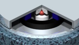
OK, here it goes. It's a combination of the ball radial bearing and the magnetic axial bearing.
Central is the radial ball bearing. Here a 20mm diam ball in 2 cups. Then there are 2 magnets (black and blue), same as in a loudspeaker. These have an axial field. The platter and static bearer are steel. So the repulsive force acts between the magnets, and the rims of the platter and the bearing. This is a closed system, only at the rim there is a fringe fields, but the strenght of this field is radial symmetric. So the cartridge is not in an AC field of the bearing, and the whole is not cogging. If needed, the platter/bearing can be made larger than the LP to get the fringe field out of the way.
Don't know about availability of loudspeaker magnets, but if needed a makeshift solution can be found by sandwiching several disk magnets between the bearer and a steel ring covering the magnets (like used in the large focal speakers).
My experience with tape/mat magnets are that they do not have a large field. Good for fridge magnets.
Yes, you will need to experiment a bit to get it round, or get a printshop to do it on a plotter. It will be a minor cost compared with the rest.
Attachments
Looks good. More machining required, i expect, than the air bearing idea.
Speaker magnets should be pretty easy to get -- i know i have many here, matched pairs might be a bit harder to scrounge (hate to "disassemble a working set of 12s for the magnets).
dave
Speaker magnets should be pretty easy to get -- i know i have many here, matched pairs might be a bit harder to scrounge (hate to "disassemble a working set of 12s for the magnets).
dave
- Status
- Not open for further replies.
- Home
- Source & Line
- Analogue Source
- Let's make a DIYAUDIO TT