
Back from the family programming and now starring at goats. And still learning how to not fully paint by numbers.
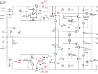
Still troubleshooting the 30v version. With a programmed bias of 72mA and 38V raw DC, it seems the R3||R4 and R5||R6 shunt resistors may be under spec'ed at 1/4W? They measure OK when cold but might 'short' if overheated? Schematic for ref below.

Still troubleshooting the 30v version. With a programmed bias of 72mA and 38V raw DC, it seems the R3||R4 and R5||R6 shunt resistors may be under spec'ed at 1/4W? They measure OK when cold but might 'short' if overheated? Schematic for ref below.
Thank you ZM. The learning curve is steep for this Dane. Those must be current programming and not shunt resistors.
How about D5 and D6, is 0.5W rating ok there?
How about D5 and D6, is 0.5W rating ok there?
Thanks ZM.
Just realized I put 1000uF in the C1/2/3/4 rather than 470uF, cause those were on hand for 50v. Would that be enough to aggravate that circuit? Likely not as it runs OK on the negative rail.
Back to staring and swapping parts.
Just realized I put 1000uF in the C1/2/3/4 rather than 470uF, cause those were on hand for 50v. Would that be enough to aggravate that circuit? Likely not as it runs OK on the negative rail.
Back to staring and swapping parts.
Back to staring
this change, inserting two 100R resistors, should help to make it foolproof for increased voltages, during power on
no need for that in my present constructions, none having critical rail value
Attachments
Thanks ZM.
I will likely resort to building a fresh 30V version, being extra anal about every detail and soldering. Parts arrived over Xmas but I have been reluctant to throw in the towel on this one ... and was busy celebrating winter solstice.
I will likely resort to building a fresh 30V version, being extra anal about every detail and soldering. Parts arrived over Xmas but I have been reluctant to throw in the towel on this one ... and was busy celebrating winter solstice.

Built a new, red version and it works as intended @30V. It also makes the D1 IV stage sing.
Thanks for the patience and assistance ZM 🙏

Thanks for the patience and assistance ZM 🙏
It has been too long since I unmounted the onboard PSU of the D1 to truly say anything meaningful. It recall the D1 sounding a bit 'hot' with the onboard PSU, which it doesn't with the GG. But that could just be more hours on the D1, or my imagination. The D1/GG combo sounds delightful. It has a naturalness and speed to it, and (at the moment) I prefer it over the Burson opamp IV powered by GG.
If it stays on top of the 'Lego DAC hierarchy', I may need a second GG for dual-mono.
Thanks again for these treats.
If it stays on top of the 'Lego DAC hierarchy', I may need a second GG for dual-mono.
Thanks again for these treats.


Noticed Q4 running red-hot today. On the first build it was Q3. Anyway, the voltage is still regulated correctly to -30V, but the bias is off with the voltage sag across the current programming resistors (R5||R6, 9R combined) being 1.75V whereas the other rail measures the expected/programmed 0,65V. Of course, I only saw the note about adding the 100R resistors after this second shunt was assembled, but will need to add these. I imagine JFET2, T2 and/or Q2 are done - any guess or just replace the three of them? I can salvage parts from the "black 30v shunt" 😆this change, inserting two 100R resistors, should help to make it foolproof for increased voltages, during power on
Thanks ZM.
For the 100R, do I need to cut the copper trace where the resistor connects? Or lift a leg from the transistors?

For the 100R, do I need to cut the copper trace where the resistor connects? Or lift a leg from the transistors?
- Home
- Amplifiers
- Pass Labs
- Let's discuss ZM's Good Gemini shunt