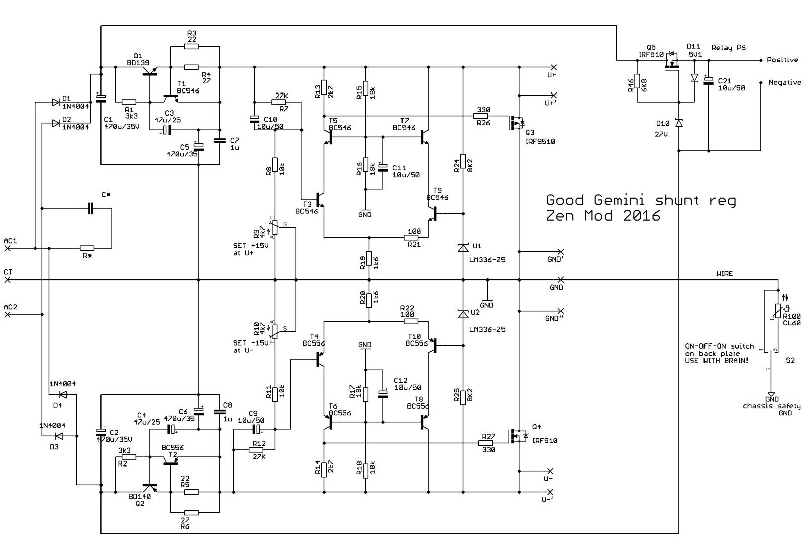
The shunt was shown as a brother of Iron pre and Iron pumpkin and was partnered with a capacitance multiplier.
http://www.diyaudio.com/forums/pass-labs/293169-whats-wrong-kiss-boy-19.html#post4883680
I would like some help discussing its Vout range and load current limits to see if it could fit any other projects like the B1, the BA-3 or even digital stuff.
http://www.diyaudio.com/forums/pass-labs/293169-whats-wrong-kiss-boy-19.html#post4883680
I would like some help discussing its Vout range and load current limits to see if it could fit any other projects like the B1, the BA-3 or even digital stuff.
Output max 45mA adjustable between 14.2V and 18.5V , negative side same thing.
Input min 4volts extra.
Somewhat over the hill for my taste.
Mona
Input min 4volts extra.
Somewhat over the hill for my taste.
Mona
Let's say for BA-3 for starters.
So it would be nice to have 25-30V range at 150-200mA to allow for some hotrodding and output biasing experimentation.
So it would be nice to have 25-30V range at 150-200mA to allow for some hotrodding and output biasing experimentation.
confirm:
-Ba-3 , not balanced
-one Good Gemini per channel
- +/-24Vdc , ~55mA , V/A per channel consumption
-Ba-3 , not balanced
-one Good Gemini per channel
- +/-24Vdc , ~55mA , V/A per channel consumption
Not very much to change but the BD's and IRF's must be better cooled.Let's say for BA-3 for starters.
So it would be nice to have 25-30V range at 150-200mA to allow for some hotrodding and output biasing experimentation.
Mona
Attachments
cooling - conditio sine qua non
200mA is way too much for 55mA A class stage load
matter of principle - 120mA is more than enough, when having (active) error amplifier
will post schm later tonight
200mA is way too much for 55mA A class stage load
matter of principle - 120mA is more than enough, when having (active) error amplifier
will post schm later tonight
Yes I now, 200mA is a lot.But the TS asked for it.But now he knows what to change.
With 55mA the BD139/140 can stay.
Mona
With 55mA the BD139/140 can stay.
Mona
To quote NP
Now where is my crazy hat....
🙂
Anyway, I did some reading.
If I understand this, R3||R4 sets the constant current output using
I = ~(Vbe on)/Rtot
right?
And the divider R7/R8/R9 sets the voltage?
Of course you can bias this circuit higher if you wish – 100 mA bias is perfectly OK as long as you properly heat sink Q3 and Q4, and if you are crazy (like me) you can experiment with higher bias, remembering that the parts are rated at 25 watts
Now where is my crazy hat....
🙂
Anyway, I did some reading.
If I understand this, R3||R4 sets the constant current output using
I = ~(Vbe on)/Rtot
right?
And the divider R7/R8/R9 sets the voltage?
here it is - for BA3 FE , +/-24Vdc , programmed current 120mA
yup , you got it , for programming current and for setting output voltage
however - when changing output voltage , one must maintain optimal currents both through reference diode and through voltage divider for error amp (R7,R8,R9)
reg itself is simple ...... pretty much everything is covered in & Shunty CookBook , simply because GG is smaller bro of Shunty , but not less effective
consider one important thing , pretty much covering all active electronic stages , but especially supply regs - PCB design is of same importance as circuit itself
BD139/140 are good up to 5W , if cooled properly
above that , go to BD239/240
xformer - everything bellow 56Vct (2 x 28Vac) is on your own risk, considering regular mains voltage sagging of 10% or even more
15VA per channel , 30VA for both , as minimum
first elco caps after bridge can go up , rest of them no need or counterproductive
if you want 200mA for programmed current , just change those resistors to
5R1 // 9R1
everything else as is
diss on BD :
(input V - out V) x programmed I
diss on IRF :
out V x (programmed current - load current)
yup , you got it , for programming current and for setting output voltage
however - when changing output voltage , one must maintain optimal currents both through reference diode and through voltage divider for error amp (R7,R8,R9)
reg itself is simple ...... pretty much everything is covered in
& Shunty CookBook , simply because GG is smaller bro of Shunty , but not less effectiveconsider one important thing , pretty much covering all active electronic stages , but especially supply regs - PCB design is of same importance as circuit itself
BD139/140 are good up to 5W , if cooled properly
above that , go to BD239/240
xformer - everything bellow 56Vct (2 x 28Vac) is on your own risk, considering regular mains voltage sagging of 10% or even more
15VA per channel , 30VA for both , as minimum
first elco caps after bridge can go up , rest of them no need or counterproductive
if you want 200mA for programmed current , just change those resistors to
5R1 // 9R1
everything else as is
diss on BD :
(input V - out V) x programmed I
diss on IRF :
out V x (programmed current - load current)
Attachments

and yes , I'll make more potent (current wise) pcbs , relatively soon , with CCS-es instead of R1,R2 and R24,R25
then you can use them in pumpupthevolume manner , as much you want ......
but ........that right after finishing special iron for Iron
then you can use them in pumpupthevolume manner , as much you want ......
but ........that right after finishing special iron for Iron
Should I worry that I got the musical reference? 😀
Am I getting... old? 😛
https://www.youtube.com/watch?v=w9gOQgfPW4Y
Am I getting... old? 😛
https://www.youtube.com/watch?v=w9gOQgfPW4Y
consider one important thing , pretty much covering all active electronic stages , but especially supply regs - PCB design is of same importance as circuit itself
Yeah I noticed you love your return currents 🙂
Should I worry that I got the musical reference? 😀
Am I getting... old? 😛
https://www.youtube.com/watch?v=w9gOQgfPW4Y
yup
and right after that , you can listen to https://youtu.be/PbbYn7d_W8s

aha , forgot to say
you mentioned digital , as possible area of use
nope ....... due to construction , even with possibility of major re-work , I wouldn't go bellow 10V for output voltage
simply - matter of choice ...... for 5V and similar , we need different approach
you mentioned digital , as possible area of use
nope ....... due to construction , even with possibility of major re-work , I wouldn't go bellow 10V for output voltage
simply - matter of choice ...... for 5V and similar , we need different approach
Changing BD139/140 to BD239/240 is not a good idea.Then you have to get smaller R1,R2 (need more base current) too, making poor regulation.BD139/140 are good up to 5W , if cooled properly
above that , go to BD239/240
diss on BD :
(input V - out V) x programmed I
diss on IRF :
out V x (programmed current - load current)
That's why I put darlingtons for more current, the resistors can stay as is.
Mona
you're right , I forgot to mention change in value of these resistors
however , 5W is more than enough with BD139/140
above that , I would consider something in range of BDX53/54 family
in any case , this is not exactly swiss army knife , every major change (meaning Vout/I out) demands necessary analysis , to maintain proper phase behavior of reg
however , 5W is more than enough with BD139/140
above that , I would consider something in range of BDX53/54 family
in any case , this is not exactly swiss army knife , every major change (meaning Vout/I out) demands necessary analysis , to maintain proper phase behavior of reg
- Home
- Amplifiers
- Pass Labs
- Let's discuss ZM's Good Gemini shunt