Why do you compare the 6j5 to the 12au7 when it is half of a 6sn7, or actually the 6sn7 is 2 x 6j5. The 12 au7 has a low mu but the 6j5 is a more linear tube.
I said it was very similar. Mu, plate resistance, transconductance, typical plate current, very close. I was discussing cutoff points with PRR, with respect to using diodes on the cathode, and using it to illustrate what that means. When does grid signal shut off the diode? Current at cutoff was the issue. He didn't get it.
Last edited:
Could you explain what that means in more detail? I don't get it either.I was discussing cutoff points with PRR, with respect to using diodes on the cathode, and using it to illustrate what that means.
Could you explain what that means in more detail? I don't get it either.
I referred to the 10 uA current considered cutoff for the tube. Both levels are the same for 12AU7 and 6J5. He (PRR) didn't get what nearly 0 current meant as the voltage across the diode fell to .7v. I thought anyone knows what 10uA of current means but he went into space about picoAmps then. So I told him where the citation about cutoff was defined in the RCA manual and he came back with some more gibberish.
But I don't understand what that has to do with diode biasing?I referred to the 10 uA current considered cutoff for the tube...
But I don't understand what that has to do with diode biasing?
A resistor never shuts off like a diode does. You get to use the whole 2v if a resistor is in place but you don't get the same range with an LED or any diode. The voltage on the diode comes from the voltage through the tube. It doesn't supply any voltage itself. The grid controls the current/voltage via the signal. When the voltage drops to the diode shutoff point, it's in the same condition as if the tube is in cutoff.
Merlin, your signature link takes us to a sight for aircraft engine parts. Ironically they have parts for Continental and Lycoming but not for Merlins. 😀
Oops! 😱Merlin, your signature link takes us to a sight for aircraft engine parts. Ironically they have parts for Continental and Lycoming but not for Merlins. 😀
A resistor never shuts off like a diode does. You get to use the whole 2v if a resistor is in place but you don't get the same range with an LED or any diode. The voltage on the diode comes from the voltage through the tube. It doesn't supply any voltage itself. The grid controls the current/voltage via the signal. When the voltage drops to the diode shutoff point, it's in the same condition as if the tube is in cutoff.
Ok, that is true, but how often does that happen in a tube amp with a led biasing the driver tube. Would just the noise floor be more current than you describe as the cutoff current?
I said it was very similar. Mu, plate resistance, transconductance, typical plate current, very close. I was discussing cutoff points with PRR, with respect to using diodes on the cathode, and using it to illustrate what that means. When does grid signal shut off the diode? Current at cutoff was the issue. He didn't get it.
Still, why not speak directly to the tube that i posted my enquiry about? I know you lump the 2 tubes together yet i have not seen anyone spent over a hundred dollars for a 12au7. Perhaps, the low current cutoff is different for the 6sn7? Do you know where in the tube data sheets that info is located?
The 12au7 I referrenced was just another example of 10uA being cutoff, it was on the top of my head at the time. I could have used 6sn7, too. I was adressing PRR in establishing what type of current level was considered effectively 0, because he didn't want to accept the term I used, of nearly 0 amps, when an LED was shut off. In your post above this, asking how often does it happen, I think the question is, when will it happen. When does a diode LED become reversed biased? If the diode has 1.5v across it, and the signal (-) cycle has (-)2v, is it reversed biased? Or is there still 1.5v on the cathode no matter how large the signal goes (-) on the grid, and still flowing forward current? Does the tube never see cutoff until it goes to (-)18v on the grid, (if the plate voltage is 250v.?) Never mind the grid current clipping on the (+), it's a given.
Last edited:
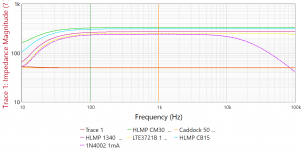
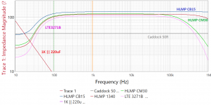
Just to throw some smoke into the discussion -- I used a current injector to look at the dynamic impedance of some older (pre-Avago) LED's and an Lite-ON Infra-Red device. First graph uses 1mA, the second 2.5mA:
Attachments
Last edited:
Pardon my ignorance but technically what is impedance magnitude. i have not seen that value on a graph before.
Pardon my ignorance but technically what is impedance magnitude. i have not seen that value on a graph before.
Ohms
The diode voltage is a function of the tube current. Voltage doesn't go 'through' anything. When the tube current gets very small, the diode voltage (i.e. bias) drops rapidly towards zero. But I don't understand what point you're making.The voltage on the diode comes from the voltage through the tube.
jackinj, those are very interesting curves. Can you elaborate on what the test signal was, and the measurement circuit.
Why is there a question mark in parantheses?
Artifact of converting image on the from the clipboard to MSPaint -- the "omega" doesn't make the transfer.
jackinj, those are very interesting curves. Can you elaborate on what the test signal was, and the measurement circuit.
Test signal was 0 dBm. When I run the test at -30 dBm the low frequency dip is much less pronounced.
Test setup is from Omicron-Labs measurement of DC-Biased impedance:
https://www.omicron-lab.com/fileadm...ased/App_Note_DC_Bias_Impedance_Caps_V2_0.pdf
Thanks 🙂
For viewers without calculators, could provide those test signal levels in mA rms or pp?
For viewers without calculators, could provide those test signal levels in mA rms or pp?
The diode voltage is a function of the tube current. Voltage doesn't go 'through' anything.
The source of the voltage on the cathode is the voltage from the plate. Pull the cathode resistor and put your meter on the K pin. Wiz...
- Home
- Amplifiers
- Tubes / Valves
- LED tube biasing, pros and cons