FYI, I've said it before, I'll say it again: as explained in my book, feeding extra current into a bias LED in an attempt to reduce its dynamic resistance will increase tube distortion. This is because it increases the forward (bias) voltage which worsens tube distortion at a faster rate than any improvement you may get from reduced LED resistance. Admittedly the degradation is often extremely small, but still, you end up burning extra current to get fractionally worse performance, and why would anyone want to do that?..
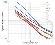
For interest, here are some mesaurements I made of dynamic resistance in some LEDs:
For interest, here are some mesaurements I made of dynamic resistance in some LEDs:
Attachments
Last edited:
Yes, this is evidenced in my book (distortion in tubes is so high that noise has negligible contribution above ~1Vrms output, typically).
Junction diodes in general do not "shut down". A plain Si diode conducts at 0.5V, 0.4V, exponentially over many decades of current.
The characteristics curves of LED's shows the current becomes nearly 0 around .7v. Stacking 3 of them would bring the turn off voltage to @ 2.1v. So if the grid signal is high enough the stack is going to essentially shut down in the negative portion and clip as if it was AB1 biased. That's about 50% loss in (-) swing.
I don't know your book...i'm sorry for that! Could you point it to me, please?Yes, this is evidenced in my book (distortion in tubes is so high that noise has negligible contribution above ~1Vrms output, typically).
Sure! 🙂I don't know your book...i'm sorry for that! Could you point it to me, please?
ValveWizard
Designing High-Fidelity Valve Preamps - Merlin Blencowe - Google Books
Last edited:
There are LEDs 2.8Vf 1.5mA?
This is as close as it gets to your requirement (i.e. basically perfect). It's white.
https://docs-emea.rs-online.com/webdocs/0e76/0900766b80e762c9.pdf
I have never used it. So you need to take a risk!😀
The characteristics curves of LED's shows the current becomes nearly 0 around .7v.....
What is "nearly zero"??
Current is a Real number and can be "infinitely small" without being zero. We have to put numbers on things.
My sim shows 0.7V happens at 1.4 PICO-Amps. I do not trust this result even to a factor of 1,000. However even if we assume Nano, even Micro-Amps we are far-far-far below the typical 0.1mA-10mA operating zone of small tubes. A class-A tube idled at 1mA would typically swing at-most 0.5mA-1.5mA to stay linear. We are never going to be down below a microAmp.
Note current is plotted log-scale.
Attachments
We are never going to be down below a microAmp.
A 12au7 is considered in cutoff @ 10 microAmps. The 6J5 at issue in this thread is very similar.
Last edited:
By pass with a electrolitic cap reduce the flicker noise of the LED.
First: note that Merlin's (and many others') data shows LED dynamic impedance at typical tube currents down below 50 Ohms, below 20 Ohms at higher currents. This is very nearly loudspeaker-cap territory. And "subsonic" flicker affects perception even if it is not reproduced in the room, by flickering intermodulation byproducts. To bypass only to 8Hz we need maybe 1,000uFd. Which is not "large" in today's cap market, but may still be a tight fit in a neat compact layout.
Do LEDs even have flicker noise?
Yes, everything does.
But respected designers advocate LEDs as low-noise voltage references. I believe I have seen it in Jung but he is not alone.
And an LED biasing a vacuum tube, the LED is the least of our flicker.
- The LED dynamic impedance is like 50 Ohms while the tube cathode dynamic impedance is typically over 500 Ohms. That's already a 3:1 difference in noise voltage.
- The LED is near room temperature while the tube cathode is HOT, 3X hotter absolute temp. That's another 2X-3X rise of noise voltage.
- While flicker seems to be inevitable throughout the universe, our devices display variable flicker which appears to be related to material contamination. In tubes the problem is difficult and was only reduced for special tubes. In semiconductors, especially MOSFET, contamination does terrible things to Yield, which is key to Profit, so Grove and others worked very hard on purer crystals, and indirectly got low flicker noise.
On the subject of "noise": I moved out of my last house where a trombone player practiced outside in the summer. Just today a tromboner started across the street. I'm not against trombone in its place: a band that I want to hear. But un-asked-for unpolished flourishes on trombone is pretty tough.
A 12au7 is considered in cutoff @ 10 microAmps.
Citation?
The ~-24V for 10uA in the 12AU7 data does not say "cut-off". It is a reference point for curve consistency.
Note also that in a day before better measurement techniques, a 50uA meter would be the most common low-I meter. 10uA on 50uA scale can be read quickly by unskilled workers. But it is arbitrary. Just like the Vto numbers on JFETs, which are conventionally read at a current which is far from "true cutoff", but rather more convenient in high volume testing.
But we'd normally run a 12AU7/6J5 at 1mA to 10mA. Taking 3mA for example, we would swing it 1.5mA-4.5mA for "full output" of 5% THD. The GE R-C chart suggests conditions like 1.5mA idle and 0.57mA peak swing, say 0.9mA-2.1mA. Nowhere near microAmps.
Citation?
The ~-24V for 10uA in the 12AU7 data does not say cut-off. It is a reference point for curve consistency.
RCA manual RC-21 page 71.
RCA manual RC-21 page 71.
http://www.tubebooks.org/tubedata/RC-21.pdf
I'm not finding any mention of current, only voltage. IAC this is not a strict definition of much of anything, but a guide to type selection.
Attachments
Using an LED amounts to "fixed bias"; the variation of Vgk is hardly affected by tube voltage or current.
In general design, fixed bias implies good control of the other electrode voltages or accepting current changes very much larger than the voltage changes causing them.
At one extreme tube dissipation goes up even faster than the usual approximately-square relationship. If we are pushing rated Pdiss, and our wall-voltage rises, the tube roasts sooner than we might expect from resistor-bias experience.
OTOH a low supply voltage may drop tube current much lower than we expect, reducing both gain and swing.
I simmed how plate voltage varies with B+ for a very wide range (1V to 500V).
Where do we want plate to be? For ideal device and infinite load, half of B+ is reasonable for symmetric signals (or asymmetric sounds of unknown polarity). For real devices and loads some other value may be optimum for swing. 12AX7 is a high-resistance tube, not much more conductive than typical loads, and a high-side bias near 2/3rd may be a good trial value.
Re-plotting plate voltage as fraction of B+, we see the resistor-bias scheme holds 0.67-0.7 of B+ for any reasonable supply voltage. (This sim is not to be trusted too far below 100V because contact-potentials are not modeled; but experience says we can go well below B+=100V before trouble arises.)
OTOH the battery and the LED bias are "stuck to B+" until B+ comes over 140V. Even at 250V of B+ we have only 20% or 50V across the load resistor; the resistor-bias scheme has 80V on the plate resistor. However at high B+ the relative plate voltage goes low, eventually going lower than optimum. (For less-insane B+ values we should probably re-bias the whole stage. However we only have limited choice of LED voltages.)
We see that, for 12AX7 and a Red LED, the bias is just awkward until we get to higher B+. And indeed the killer app for an LED under a 12AX7 is a Guitar amplifier (high B+) and especially its Tremolo oscillator (where subsonic response is essential).
OTOH the supply sensitivity is not as bad as I'd innocently thought. For a +/-16% swing like 300V-400V, the plate voltage variation is <8% which is usually plenty stable.
Attachments
As I said before, the best way is to use cathode LED bias of a triode with Gyrator anode load. Low dynamic resistance of LED + high dynamic resistance of anode load, but stable anode voltage that does not depend on brand or age of the tube used.
A 12au7 is considered in cutoff @ 10 microAmps. The 6J5 at issue in this thread is very similar.
Why do you compare the 6j5 to the 12au7 when it is half of a 6sn7, or actually the 6sn7 is 2 x 6j5. The 12 au7 has a low mu but the 6j5 is a more linear tube.
The 12AU7 and 6SN7 are similar: similar mu, similar gm, similar suggested bias, similar suggested applications. They are not identical, but this was never claimed.
No, it doesn't. Class A says the tube is conducting over the whole signal period, without any plate current cut-off. If there were no plate current swings, there would be no voltage swing across the load resistor. The only thing we could say is that the average plate current remains constant.However in real life, using class A small-signal circuits, since the plate current of the tube stays constant, Vf of the LED stays fairly constant too.
Best regards!
- Home
- Amplifiers
- Tubes / Valves
- LED tube biasing, pros and cons