AndrewT said:Hi Jens
Any chance you can check the numbers without the variac in front of the PSU?
The outputs @ 4R & 8R from the loaded Vrail values quoted are pretty good.
It appears to be the PSU that is strangling the output.
No, I'm sorry, the vario transforer is needed in my current setup.
I will know more when I build the final powersupply.
\Jens
JensRasmussen ,
Please let me know of the protection test with input drive at supply +/-80v
Rajeev
Please let me know of the protection test with input drive at supply +/-80v
Rajeev
This again will depend on the regulation of the transformer used.
I will test this when I get my transformers (+-75V unloaded 1000VA)
\Jens
I will test this when I get my transformers (+-75V unloaded 1000VA)
\Jens
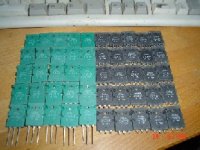
The extended leach boards have arrived. 
Jens, these are the very best boards i have ever seen.
Anyone still waiting for your boards to arrive is in for a treat.
I do not desire to build another chassis for the Super Leach so i am going to build a universal one.
I decided to go full throttle on the extended leach.
Meaning:
i am placing the board on a heatsink, which will be mounted in a heatsink tunnel.
The tunnel will be U-shaped, welded from 10mm alloy plates.
The ampboard-heatsink module will slide in the U-channel, fastened on the sides with bolts.
The tunnel will have doubled dual-prop vents, two vents behind eachother, 4 vents per channel
dual-props you see with airplanes for noise reduction.
Cruiseships have Dutch Lips dual duct screws, for saving fuel and noise level reduction, like the Queen Elisabeth 2.
Doubling vents adds 3 dB, dualing two 80 mm 30 dB ventilators produce less noise than a single 120 mm type, with the same air flow volume.
Better even, the same flow through 0.44 of the 120mm area, which means 2.25 higher air speed.
Higher air speed means higher cooling rate.
I am aiming at a heatsink factor of 0.05.
Good enough for full class A with the extended leach, hopefully 200 watts.
The Super leach i am going to place on a similar heatsink, changing the two should be a matter of minutes.
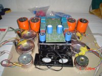
I added a picture of the initial setup with one of your boards on top of two mirrored 250mm heatsinks.
The Orange caps are 100 Volt Siemens Long Lifes, the two small 50VA toroids for the front end powersupply.
The Blue's are Sprague 200 Volt models.
The pic is for a mono setup.
Jens, these are the very best boards i have ever seen.
Anyone still waiting for your boards to arrive is in for a treat.
I do not desire to build another chassis for the Super Leach so i am going to build a universal one.
I decided to go full throttle on the extended leach.
Meaning:
i am placing the board on a heatsink, which will be mounted in a heatsink tunnel.
The tunnel will be U-shaped, welded from 10mm alloy plates.
The ampboard-heatsink module will slide in the U-channel, fastened on the sides with bolts.
The tunnel will have doubled dual-prop vents, two vents behind eachother, 4 vents per channel
dual-props you see with airplanes for noise reduction.
Cruiseships have Dutch Lips dual duct screws, for saving fuel and noise level reduction, like the Queen Elisabeth 2.
Doubling vents adds 3 dB, dualing two 80 mm 30 dB ventilators produce less noise than a single 120 mm type, with the same air flow volume.
Better even, the same flow through 0.44 of the 120mm area, which means 2.25 higher air speed.
Higher air speed means higher cooling rate.
I am aiming at a heatsink factor of 0.05.
Good enough for full class A with the extended leach, hopefully 200 watts.
The Super leach i am going to place on a similar heatsink, changing the two should be a matter of minutes.
I added a picture of the initial setup with one of your boards on top of two mirrored 250mm heatsinks.
The Orange caps are 100 Volt Siemens Long Lifes, the two small 50VA toroids for the front end powersupply.
The Blue's are Sprague 200 Volt models.
The pic is for a mono setup.
Attachments
Hi Jacco,
I'm happy that you like the boards 🙂
.... and someone said the boards are big....... 🙂
Skype me, or contact me via MSN if you get the time
\Jens
I'm happy that you like the boards 🙂
.... and someone said the boards are big....... 🙂
Skype me, or contact me via MSN if you get the time
\Jens
jacco vermeulen said:The extended leach boards have arrived.
The tunnel will have doubled dual-prop vents, two vents behind eachother, 4 vents per channel
dual-props you see with airplanes for noise reduction.
Doubling vents adds 3 dB, dualing two 80 mm 30 dB ventilators produce less noise than a single 120 mm type, with the same air flow volume.
Better even, the same flow through 0.44 of the 120mm area, which means 2.25 higher air speed.
Higher air speed means higher cooling rate.
My experience is that full speed fan is not necessary in most cases. Smaller speed is enough to cool down the heatsinks, and it results decreased noise. So, I recommend to use speed regulated fans.
sajti
For the Super Leach i am aiming at +600 watts dissipation.
The vents will be speed regulated, probably intelligently temperature controlled.
I have to get rid of 10dB minimum, probably need to derate them to half speed.
Thank you for advising , Sajti.
Chassis size will be around 24' x 16' x 8' (wxdxh)
I said your boards are too small, Jens !
But they are ever so Cool.
(I have been holding them all afternoon, feeling the weight, looking at all the smooth trace curves.)
I really do not understand that someone would like closer nesting.
No doubt that these boards make the best Leach ever.
(those small Leach guys will undoubtebly be just as happy)
I'll get the headset out of the old suitcase.
(yesterday evening they made me install a new messenger version )
)
The vents will be speed regulated, probably intelligently temperature controlled.
I have to get rid of 10dB minimum, probably need to derate them to half speed.
Thank you for advising , Sajti.
Chassis size will be around 24' x 16' x 8' (wxdxh)
I said your boards are too small, Jens !
But they are ever so Cool.
(I have been holding them all afternoon, feeling the weight, looking at all the smooth trace curves.)
I really do not understand that someone would like closer nesting.
No doubt that these boards make the best Leach ever.
(those small Leach guys will undoubtebly be just as happy)
I'll get the headset out of the old suitcase.
(yesterday evening they made me install a new messenger version
)The half voltage is quite nice idea! Most of fans have no noise with half voltage. I have class A amplifier, which use fan cooling, with speed regulated circuit, I planned. This amplifier dissipates about 240W on a single 43cm long heatsink. And the fan never riched the maximum speed...
600W is serious amount of heat. I saw the cooling tunnel of the Crest CA12, with two 120mm fans run on full speed...
sajti
600W is serious amount of heat. I saw the cooling tunnel of the Crest CA12, with two 120mm fans run on full speed...
sajti
Sajti,
any idea on the length of the tunnel on the Crest amplifier ?
I made an initial heat transfer calculation, dug up my old college
thermodynamica class books.
The entire chassis will be made of 10mm alloy, the duct will be thermally connected to the bottom of the chassis, with thermal grease.
the dual-prop vents will be contra-rotating, that should reduce noise and give better performance(i hope).
You do car racing?
thank you,
J.
The Crest has two 40cm long tunnels. The heatsinks filled up the whole 120x120mm cross section of the fan. It was really heavy!
I think that aluminium chassis would be better for cooling, due the alloy is not really good heat conductor. To connect the tunnel to the chassis is very good idea! I did it many times in my amplifiers...
sajti
Yes, I did some rallye racing, but it takes lot of money, and we didn't find enough sponsors to continue 🙁
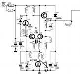
i decided to use the 300 watt/8 Giant2000 regulator for regulating the voltage on the front end of the extended Leach amp.
That amplifier used a stacked powersupply too, 15VDC on top of the 70Vdc main toroidal.
This circuit handled the voltage regulation for the entire front end including the driver section, the reason for using the BD712 that does well over 10 amps, 18 Max.
The 75 watt BD712 only has an Ft of 3 MHz.
I am going to swap that one for a faster Toshiba, or an IRF mosfet.
Basically i am going for at least 4 regulators for the front end.
For the regulator that handles the front end gain stages a 25 watt device will do as substitute for the BD712, 2SA968/2SC2238 or better.
For the regulator that does the driver stage the BD712 will be swapped for something with the same power capability or more.
Maybe a couple of them 2SA1302/3281 on a decent heatsink.
Attachments
Jens, I looked at your homepage and the picture of the step response. Did you compare the input signal also? Was it totally "clean" or did you have a small overshoot there also? What I ment was that your amp may be better than the picture wants to show.  Otherwise
http://www.delta-audio.com/Leach_Clone/Square.jpg
Otherwise http://www.delta-audio.com/Leach_Clone/Square.jpg
To Jacco : Using of faster transistors is unneccessary, 'cos output of regulator is bypased by C 33,34 which are " batery " of energy. Faster transistors can make problems at this possition.
Pavel,
you think the circuit is good as is, and good enough for regulating the Leach front stage?
I thought of emitting the caps, or placing a low value resistor between the emitter of T47 and the capacitors.
Thanks,
jacco.
you think the circuit is good as is, and good enough for regulating the Leach front stage?
I thought of emitting the caps, or placing a low value resistor between the emitter of T47 and the capacitors.
Thanks,
jacco.
I mean that it will be OK. Inrush current is supressed by R 56, so you can't change anything 😎 .
Actually UpuPMaPavel, now that you mentioned it.
I was also considering exchanging the entrance filter for more extensive R-C's, and reducing R56 to half or 1/4th and increasing C30 accordingly.
I am doubling the regulators for separate regulation of front end and driver stages anyway.
I'll take your advice and use the circuit as is.
Thank you for commenting,
J.
Hi all,
I have started work on a construction manual.
It's not done, but can be found here: http://www.delta-audio.com/temp_jens/Leach_Amp_Clone_manual_ver_0.2.pdf
I have only made the output transistor analyzes until now, but please comment on this if you have suggestions or need questions answered.
\Jens
I have started work on a construction manual.
It's not done, but can be found here: http://www.delta-audio.com/temp_jens/Leach_Amp_Clone_manual_ver_0.2.pdf
I have only made the output transistor analyzes until now, but please comment on this if you have suggestions or need questions answered.
\Jens
- Status
- Not open for further replies.
- Home
- Amplifiers
- Solid State
- Leach clone, pretty good looking