Member
Joined 2009
Paid Member
It looks to me (no expert of course) that VR1 controls the current flow through the input device, which will affect the dc operating point. So you adjust VR1 carefully before connecting any speakers until the dc voltage across the speaker terminals is close to zero, ideally less than 50mV in my opinion.
It looks like VR2 controls the current through the phase splitter, it will affect the current flow through the output devices. It will control the idle temperature/power dissipation of the amplifier and so you have to adjust slowly starting from low output current and let the heatsink heat up and settle at a steady state before adjusting if further - checking to ensure it's not overheating. You can measure the current through the output devices by measure the voltage drop across one of the output resistors such as R12 and then uses Ohms law to calculate the current.
Does this help ?
congrats on your son, sorry for the slow reply i too have a son due this year in june 🙂
what dimensions are the heatsinks ?
from memory one pot is bias the other is DC offset it would be best to contact the person who made the pcb
-Dan
what dimensions are the heatsinks ?
from memory one pot is bias the other is DC offset it would be best to contact the person who made the pcb
-Dan
Thanks Bigun! I'm going to brew some coffee and head to the garage🙂 I'll let you know what I get.
Daniel,
Congrats on your son. It is the most amazing thing ever! I love audio, but I'd give it up for good for him!
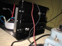
My sinks are 11.5" X 4.5" X 1.25" tall fins on a 3/8" base. There are two of these per side, so the end result is 11.5" X 9" X approximately 1.5" Here are a few snapshot of the amp coming along. I think it looks pretty nice. The top plates are perforated aluminum, and the rear plates are .25" 6061 aluminum. I'm still trying to find the optimal front cover.
Blair
Daniel,
Congrats on your son. It is the most amazing thing ever! I love audio, but I'd give it up for good for him!
My sinks are 11.5" X 4.5" X 1.25" tall fins on a 3/8" base. There are two of these per side, so the end result is 11.5" X 9" X approximately 1.5" Here are a few snapshot of the amp coming along. I think it looks pretty nice. The top plates are perforated aluminum, and the rear plates are .25" 6061 aluminum. I'm still trying to find the optimal front cover.
Blair
Attachments

OK,
Forgive my SS ignorance, but in order to bias this amp to anywhere near my understanding of biasing, the little Kermet pot is getting pretty hot.
I am clipping my meter to one side of the .1ohm resistor and the other side to get the voltage drop. Is this correct? I can only get to .02v before the pot is really hot! Any ideas?
Thank you!
Blair
that is strange the pot is hot ? that level represent 0.2 A bias.
one thing to watch is the length of those wires to the output transistors... probably wont be a massive issue but it helps to keep them as short as possible.
(although i myself have done the same thing albeit 5 cm long wires)
is the pot you are adjusting dc offset or bias ? I woudl not expect the pot to get hot
-Dan
i only ask becaue sometimes with biasing nothing happens until a point and then it biases quite quikly, my suggestion would be wind it up slowly until you see a change if it does not work you need to re-check your resistor values, transistorsplacements etc.
is the supply voltage ok ?
is the supply voltage ok ?
Well,
At this point it does not matter much. I put a flashlight on the pot, and it melted the casing and looks pretty cooked internally. It is one of those with epoxy so it was easy to see.
I have solid +/-23.8v rails. I put a signal on it with a cheap speaker despite the DC offset, and it makes aound, but not much. I really chose the wrong monoblock to try first. The other one has the board flipped and it is much easier to get to the pots.
Here is a good question for you. How long does it usually take for the transistors to get warm? When I first fired it up, it was one for five minutes or so, and they were still cool. I'm assuming that is not right.
Blair
That is not right.
normally ay a 25 degree C ambient temp
the transistor cases (circular metal cap in your case on T-03 packages)
will become hot to the touch in about minute regardless of heatsink size.
I would check the rest of the circuit - compenet in the right way round, resistor values, solder joints etc.
Hope this helps
-Dan
Member
Joined 2009
Paid Member
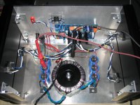
It can get pretty frustrating very quickly - most of us have been there. Don't despair, you will get it working and learn something along the way. Your chasis looks pretty nice and the wiring and layout nice and neat. Along with a professional pcb you have all the ingredients to make this a good amplifier without too much detective work.
Sometimes it works to post a good photo of your pcb, back and front sides, so that people here can give it a careful look over.
Sometimes it works to post a good photo of your pcb, back and front sides, so that people here can give it a careful look over.
Thanks!
It is not worse than any other project really. There was no smoke, or sparks so I'm not discouraged at all. It happens. I find it is best sometimes to just step away for a few days and then pick it back up. Maybe what I'll do is just wire the other amp, and fire it up since it is easier to access the pots. There are some bits and pieces in some of Hood's articles regarding VR2 needing to be a bit higher wattage value than VR1.
Blair
Here are some notes by Geoff on the design and his PCB (which I believe is the same one as on the SkyCoral.com site):
JLH-2005 – NOTES
Setting the bias can be tricky, here are Geoff's instructions:
http://www.diyaudio.com/forums/soli...-post1067918.html?highlight=geoff#post1067918
JLH-2005 – NOTES
Setting the bias can be tricky, here are Geoff's instructions:
http://www.diyaudio.com/forums/soli...-post1067918.html?highlight=geoff#post1067918
Awesome!! Thank you!
I was unable to find anything like this on the web.
I assume you have built one of these? Are 1/2W Kermet pots sufficient?
Thanks!
Blair
I was unable to find anything like this on the web.
I assume you have built one of these? Are 1/2W Kermet pots sufficient?
Thanks!
Blair
OK,
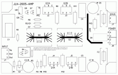
The first thing I noticed looking at Geoff's boards is that for Q4, he only has one installed. I pulled the one he has missing out of the circuit and fired it back up. I have essentially no emmitter voltage on Q2 and Q2A despite having about 12.2v on the base. Any ideas? Do you think I cooked a 2SA970 because I had both installed?
Blair
Here is an explanation and a view of the board. Why is there two positions for Q4? I see the pinout is different, so I assume it is to allow for different transistors? It appears you cannot read my writing on the image, but it says that I pulled the one to the right in the square, and am asking if you think I damaged the one to the left in doing this. Also, is this the reason for my not being able to adjust the DC offset since it appears that I have nothing on my emmitters of Q2 and Q2A?
Thanks for everyone's assistance. I'll leave you guys alone until I find a new project😉
Blair
Thanks for everyone's assistance. I'll leave you guys alone until I find a new project😉
Blair
Attachments
OK,
Not really a stroke of genious, but rather an observation. Looking at the JLH site, I see that Q5-7 are recommended to be 2SA970s, but the pinout on the board is different than the 2SA970. Does anyone know what transistor the pinout is for? I suppose I could install the 2SA970 backwards and reverse the C and B pins, but obviously the board was made for a different transistor.
Anyone know what the pinout fits?
Thank you!
Blair
Member
Joined 2009
Paid Member
I would follow the pin out on the board - regardless of which device you use make sure the emitter pin goes in to the 'e' pcb hole etc.
oh, I see the problem, the pcb shows two different pin outs for one device.
Ok now I get it, two pin outs provided to allow for two different device, but only 1 is to be installed. I can't for the life of me understand why anybody would design a pcb like that. Now I'm confused.
Now I get it again, the pcb is trying to cater for a choice of devices - it's trying to be helpful.
so good that you took one of them out - you only really need 1 device in there.
sorry I didn't add any value here ...
Last edited:
No problem. You are spot on with your comments. It is verifying that I'm not nuts!
I just hope that I did not clip off the leads on my 2SA970s too short for this reroute, and that I did not damage any of them. They were the only part I had to order! 😡
The funny thing is that the recipe calls for 2SA970s, but the board is not laid out for them. I need to turn them around and flip B&C to get them to work.
Thanks!
Blair
Here are some notes by Geoff on the design and his PCB (which I believe is the same one as on the SkyCoral.com site):
JLH-2005 – NOTES
Setting the bias can be tricky, here are Geoff's instructions:
http://www.diyaudio.com/forums/soli...-post1067918.html?highlight=geoff#post1067918
Hey Paul,
Looking through the link you sent, I can confirm from looking at your boards that they are the same layout. What did you use for Q5-Q6? The 2Sa970 does not use this pinout.
Thank you!
Blair
- Status
- Not open for further replies.
- Home
- Amplifiers
- Solid State
- Le Monstre vs. Parallel JLH class A?