
Beautiful results!
Have you listened to the creation and able to give some listening impressions?
How does it perform in a square wave signal test?
Some other questions:
What is your considerations on using auto-transformer and/or the IC based headphone amp except to obtain a gain of a total of 18dB in the front end?
What is the total gain of the amplifier, in other word, what is the gain in the output stage?
regards
There is no principle difference with LUFET when talking about power device, LD101dD+N-Mos and P-Mos push pull. Only with simplified bias circuit.
And I am trying to use audio headphone amp front end instead of Fjet buffer.
And I am trying to use audio headphone amp front end instead of Fjet buffer.
Yes I saw the headphone amp front end, good idea to combine gain from op amp and EDCOR.
so the output PP stage should have the same "sound signature" as the LuDEF PP stage.
can the LM385-ADJ be replaced by a low current (0,04mA) version of TL431 ?
it is used in F4: TLVH431 or NCP431 or SC431 or AP431
so the output PP stage should have the same "sound signature" as the LuDEF PP stage.
can the LM385-ADJ be replaced by a low current (0,04mA) version of TL431 ?
it is used in F4: TLVH431 or NCP431 or SC431 or AP431
Last edited:
Mouser: 621-AZ431LAZTR-G1
1.25V voltage reference.
I just put 0.11 on S of LD1014D, and 0.22 on PMos. The bias with the circuit is rock solid.
I haven't tested reduce them yet.
1.25V voltage reference.
I just put 0.11 on S of LD1014D, and 0.22 on PMos. The bias with the circuit is rock solid.
I haven't tested reduce them yet.
Last edited:
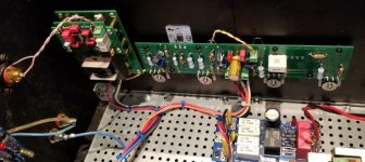
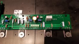
Power stage
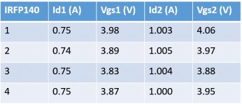
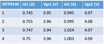
Output device used.
LD1014D, IRFP140 and IRFP9140.
1. From Vds-Ids-Vgs curves of two LD1014D, the initial bias points are selected. Vgs=-1.1V, Vds=2V, Id=1.5A.
2. For P-Mosfet, Vgs=-4V (at Id=0.75A)
3. P3 set to smaller than (V+/6-1)*4.7K,
4. Power on the amp board without LD1014D and Mosfet
5. Measure the voltage on the voltage reference and adjust P2, it should be ABS(Vgs(LD1014D)+Vgs(Mosfet)), here (-1.1-4)=5.1V
6. Measure the voltage between the gate of LD1014D and Mosfet, adjust P3, it should be smaller that -1.1-(-4)=2.9V
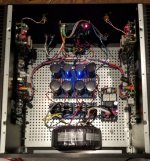
7. Power off, mounting and soldering LD1014D and Mosfet on the heat sink and the board,
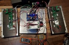
8. Used two industrial SWPS as +/- 24V
Output device used.
LD1014D, IRFP140 and IRFP9140.
1. From Vds-Ids-Vgs curves of two LD1014D, the initial bias points are selected. Vgs=-1.1V, Vds=2V, Id=1.5A.
2. For P-Mosfet, Vgs=-4V (at Id=0.75A)
3. P3 set to smaller than (V+/6-1)*4.7K,
4. Power on the amp board without LD1014D and Mosfet
5. Measure the voltage on the voltage reference and adjust P2, it should be ABS(Vgs(LD1014D)+Vgs(Mosfet)), here (-1.1-4)=5.1V
6. Measure the voltage between the gate of LD1014D and Mosfet, adjust P3, it should be smaller that -1.1-(-4)=2.9V
7. Power off, mounting and soldering LD1014D and Mosfet on the heat sink and the board,
8. Used two industrial SWPS as +/- 24V
Attachments

Last edited:
A lot of unexpected hurdles appeared:
1. First wrong voltage reference ordered.
2. Some 2.5V TL431 has high working current, may not work properly.
3. It was found Pin 2 and 3 were laid out wrongly on PCB.
4. Very low frequency oscillation when connected to Focusrite Scarlet Solo USB interface.
5. SMPS not have enough current
1. First wrong voltage reference ordered.
2. Some 2.5V TL431 has high working current, may not work properly.
3. It was found Pin 2 and 3 were laid out wrongly on PCB.
4. Very low frequency oscillation when connected to Focusrite Scarlet Solo USB interface.
5. SMPS not have enough current
Attachments


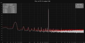
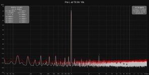
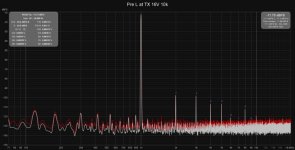
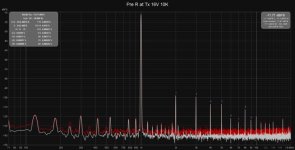
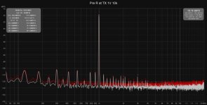
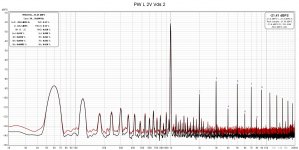
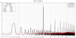
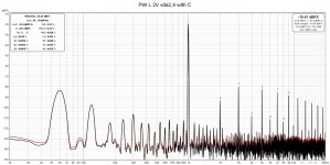
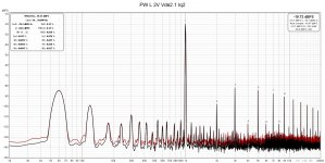
Measurements
1W at 8 ohm, Iq 1.5A to 2A, Vds 1.5V to 2.5V, THD+N almost not change much. Odd harmonies dominating, around 0.15% THD+N.
Tried a lot of things, even Vds of LD1014D lowered to 1V, the THD+N signature doesn't change much.
I have no ideal what is going wrong.
So further tweaking is needed.
1W at 8 ohm, Iq 1.5A to 2A, Vds 1.5V to 2.5V, THD+N almost not change much. Odd harmonies dominating, around 0.15% THD+N.
Tried a lot of things, even Vds of LD1014D lowered to 1V, the THD+N signature doesn't change much.
I have no ideal what is going wrong.
So further tweaking is needed.
Attachments
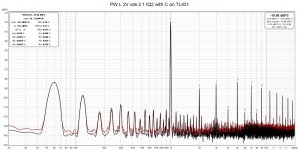

maybe this is the front end spectral signature?
have you tried the output stage without gain stage?
have you tried the output stage without gain stage?
- Home
- Amplifiers
- Pass Labs
- LD1014D Id-Vds-Vgs Curve