And I haven't found any LTSpice model close to real world in the forum.
wwwtttwww, Search on me, from years ago. Maybe a Magura thread? I did a crued modification of the Toshiba model and created a LU1014 model for Pspice that worked surprising well. You can get the data out of it if you can find it.

Also, ZM I think had great results in the LU DEF thread or what ever its called.
Last edited:
Use SIT model to generate LD1014D model
So far I haven't see any LU1014D or LD1014D model, which is close enough for LTSpice.
In the area Vds 0-3V, Id 0-4A, LU1014D is like a SIT. Then why don't we use SIT model to do sim with LTSpice if we can find K, MU, N, X, Vct with a LD1014D
The detailed method is shown in:
Using Microsoft Excel Solver to Find a SIT Sim Model Parameters(1)
“A Concise Model for Static Induction Transistor IV Characteristics” - Michael Rothacher
In his publication, a equation is given to find model for simulation:
Id=K*(Vg+Vct+N*LN(Vd)+Vd/Mu)^X
.SUBCKT TFH51S D G S
+ PARAMS: K=0.157 MU=7.3 N=2.24 X=1.51 VCT=0.0
B1 D S I=K*PWR(URAMP((V(G,S)+VCT)+(N*LN(V(D,S))+(V(D,S)/MU))),X)
.ENDS TFH51S
Use the measured data of #10 LD1014D in post #5, used the method above and found the parameters.
The model for #10 LD1014D is
*--------------------------------------------------
*LD1014D_Min
*GENERATED BY Min
*MODEL RANGE: 3V, 4A
*--------------------------------------------------
.SUBCKT LD1014D_Min D G S ; Drain Gate Source
+ PARAMS: MU=5.93 X=15.31 K=0.51 N=0.121 VCT=1.98 RG=2MEG
*--------------------------------------------------
B1 D S I=K*PWR(URAMP((V(G,S)+VCT)+(N*LN(V(D,S))+(V(D,S)/MU))),X)
R1 G S {RG}
CGS G S 784P
CGD G D 363P
CDS G S 104P
.ENDS LD1014D_Min
*--------------------------------------------------
Attachments


Compare with other model
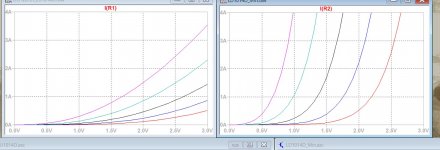
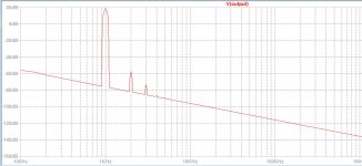
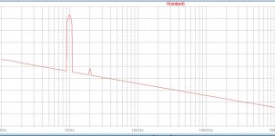
This is the one I found in the forum, which shows the triode curve, but with too low S.
.SUBCKT LU1014D 1 2 3 ; D G S
+ PARAMS: a=21.7924 b=4.5599 c=10.2887 d=9.1318 e=61.579
+ f=0.5726 g=-16.0443 h=71.8659
G1 1 3 Value={(a+b*V(1,3))*(1-V(2,3)/
+ (c+d*V(1,3)))**(g+h*V(2,3))*TANH((e*V(1,3))/
+ (a*(1-f*V(2,3))))}
.ENDS LU1014
See the picture, the left is the curves calculated with this model. The right is calculated with the new model. You can see a big improvement.
Attachments
Last edited:
The simplest LuFet Sim
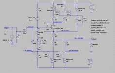
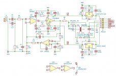
The circuit is very normal LuFet. The target in mind is to reuse all components of my F5 turbo V2 setup at +/-32V rail. Iq target is 2A. To reduce thermal load, two IRFP240/9240 are used.
Using same bias setup circuit shown in the simplest DefiSIT amplifier with voltage shifter. Offset_Adj is used as amp's offset adjustment and voltage shifter. Its voltage should be close to the sum of the Vg of LD1014D and 9240. Two diodes and a red LED are used as temperature compensation. Vds_Adj is used to set the Vds of LD1014D.
Attachments
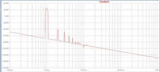
The sim with the LD1014 in post #24
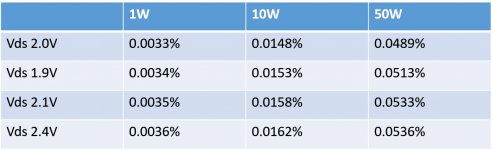
The sim is run at Iq 2A, the Vds of the LD1024D varies from 1.9V, 2.0V 2.1V and 2.4V.
For a LD1014D with a good "curve" (#10), the distortion doesn't change much when Vds changes a lot (1.9-2.4V).
The sim is run at Iq 2A, the Vds of the LD1024D varies from 1.9V, 2.0V 2.1V and 2.4V.
For a LD1014D with a good "curve" (#10), the distortion doesn't change much when Vds changes a lot (1.9-2.4V).
Attachments
The sim with a LD1014D(#6) in the middle of the bunch.
Picked up LD1014D #6, whose curve is in the middle of the 20pcs. This Lu1014D shows a slight saturation at Vgs=-1 and Vds over 2.5V.
The model will have more error when the curve has more bending or in this "negative" property area (Vds reduces when Id increases). May it have a "special sound"? No idea.
Vds could be lowered to minimize this effect. But in the sim with this #6 LD1014D, the distortion does change too much as well. In the real world it may have more.
Attachments

Last edited:
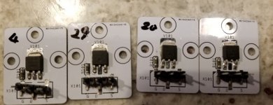
Here’s my measurement of received LD1014D batch from suspect Chinese sources. Different part packages and DOA parts inside what looks, at first sight, as original Lovoltech packaging (it is not).
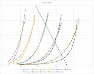
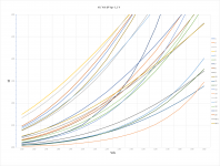
As expected I-V curves are wide spread and I had to group parts in four different Vgs batches, to stay within reasonable current. Upper limit was set at 6A, but chart is cut off at 3A. Even at 6A I didn’t measure decreasing current at higher Vds like found on wwwtttwww’s measurement. It was always increasing according to the triode curve.
First batch measured at -1.1 Vgs, contains also two matched LU1014D from PTC (Papa’s Treasure Cave). Their well-matched curves are right in the middle of pack.
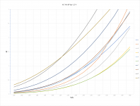
Second batch is measured at Vgs -1.3 V. I didn’t finish charts for the rest as those two are enough for me to make a point.
All parts exhibit proper triode like curve. In fact, if one would fiddle with Vgs, all curves would end as being pretty close. On those two charts, it is possible to find 3 to 4 pairs of enough well matched LD1014D. So, those LD1014D are great bang for the buck.
As expected I-V curves are wide spread and I had to group parts in four different Vgs batches, to stay within reasonable current. Upper limit was set at 6A, but chart is cut off at 3A. Even at 6A I didn’t measure decreasing current at higher Vds like found on wwwtttwww’s measurement. It was always increasing according to the triode curve.
First batch measured at -1.1 Vgs, contains also two matched LU1014D from PTC (Papa’s Treasure Cave). Their well-matched curves are right in the middle of pack.
Second batch is measured at Vgs -1.3 V. I didn’t finish charts for the rest as those two are enough for me to make a point.
All parts exhibit proper triode like curve. In fact, if one would fiddle with Vgs, all curves would end as being pretty close. On those two charts, it is possible to find 3 to 4 pairs of enough well matched LD1014D. So, those LD1014D are great bang for the buck.
Attachments

Just throwing this out to the OP or anyone that has the means and time to test and match these ld1014d.
I bought a 100 from the original seller that wg45 and/or xrk mention in the group buy thread for the adapter boards.
They had good results with testing and matching from what I gathered.
If you’d like to test and match from my batch I’d be more than willing to drop these in the mail to you in exchange for a cut of the good resulting matches.
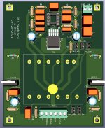
The Front End
The main concept is still Edcor auto-transformer. But in the front of it, the TI standard headphone amp circuit(LM4653+LME49600) is used to provide portion of voltage gain. The while gain is targeting X8, the Edcor provides 2X, the headphone amp provides X4 gain.
The main concept is still Edcor auto-transformer. But in the front of it, the TI standard headphone amp circuit(LM4653+LME49600) is used to provide portion of voltage gain. The while gain is targeting X8, the Edcor provides 2X, the headphone amp provides X4 gain.
Attachments
From 20 pcs, 5 are bad, no readings. The rest 15 are OK, but their curves are widely distributed(vgs at -1V).
Two from wg45 are matched very well.
Of the 5 that you think are bad, tray raising the Vgs to several volts more negative than you think should work to turn off the part. Once you know what Vgs turns off the part ( say less than 1uA Ids) , then figure out what Vgs gives you 1mA Ids. Those are your rudimentary figures of merit for evaluating your stash without needing a heatsink or any fancy equipment. You may find out that all of your parts are functional; just very wide dispersion of Vgs.
The parts that are bad are the ones that can never be turned off.
Interesting!
Interesting project!
I will for sure follow your progress.
It might deserve a new thread?
lydlaug
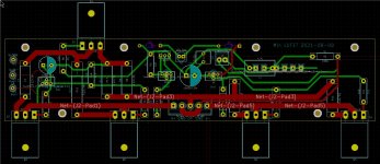
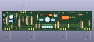
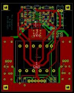
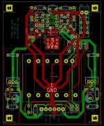
For testing the circuit, PCB is designed. They are on the way to me.
Interesting project!
I will for sure follow your progress.
It might deserve a new thread?
lydlaug

- Home
- Amplifiers
- Pass Labs
- LD1014D Id-Vds-Vgs Curve