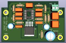
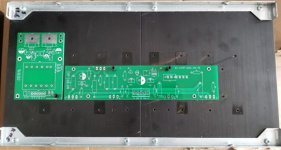
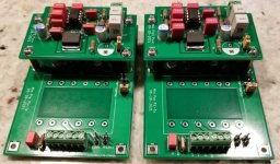
voltage amplifying board + Base board configure
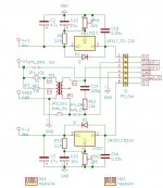
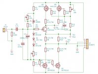
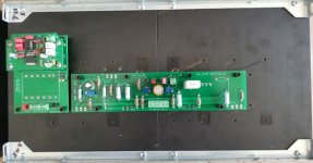
Like M2's and V-Fet input stage (Mark's design), the Lufet driving stage is divided into two boards: the base board, on which the line regulators and the transformer are mounted; the amp board, the op and headphone amp are soldered.
Jumpers are put in for convenient modes: high gain, low gain, IC direct output(no transformer), auto-transformer and normal transformer.
Attachments
Last edited:
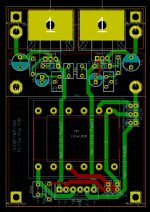
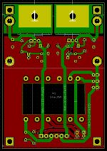
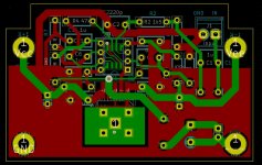
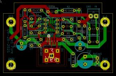
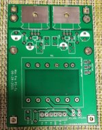
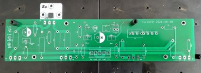
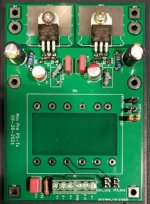
the daughter board
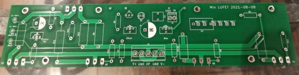
Use 4 mounting holes on the board as V+, V-, GND and Output. It can be easily connected to the base board.
In the future, different daughter board can be designed and tested based on personal tastes.
Use 4 mounting holes on the board as V+, V-, GND and Output. It can be easily connected to the base board.
In the future, different daughter board can be designed and tested based on personal tastes.
Attachments
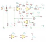
But the bias circuit is simplified.
LM385 is used as offset adjustment and the voltage shifter. The voltage should be Abs(vg1+Vg2).
To reduce the stress on MosFet, two mosfets are parallel.
PS: Wrong symbol for IRFP9240. (P-Channel)

Mine were 5 times that price for 8,000 pieces. Plus shipping...
Mine were 5 times your price, plus bank charges, plus shipment.
But pre-matched by Grey Rollins those days.
And have no problems getting quads curve traced to 0.3% in a triode cell.
And very good yield from a batch of 100.
Patrick
Many of the Spice models of LU1014 are miles out and do not reflect reality, especially in triode mode.
The only one that works for me (in triode mode) is from DIYA member Kekso22 :
LD1014 SPiCE models
Attached is, as an example, a circlotron power follower with the triode cell, al la Zen V9.
Note high Zout.
Patrick
.
The only one that works for me (in triode mode) is from DIYA member Kekso22 :
LD1014 SPiCE models
Attached is, as an example, a circlotron power follower with the triode cell, al la Zen V9.
Note high Zout.
Patrick
.
Attachments
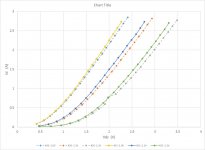
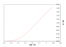
This is a typical quad set in a 200mA triode cell for headphones :
LU1014-00164 -1.422 0.957
LU1014-00234 -1.421 0.959
LU1014-00191 -1.421 0.961
LU1014-00139 -1.423 0.962
First value is Vgs at 200mA.
Secind value is transconductance at 200mA.
Patrick
LU1014-00164 -1.422 0.957
LU1014-00234 -1.421 0.959
LU1014-00191 -1.421 0.961
LU1014-00139 -1.423 0.962
First value is Vgs at 200mA.
Secind value is transconductance at 200mA.
Patrick
the model you posted can be used as in general sim.
if you want really go to the detail of sim, I think the best approach may still be the methods published by Michael Rothacher. then you find the parameters, which fit you individual component.
if you want really go to the detail of sim, I think the best approach may still be the methods published by Michael Rothacher. then you find the parameters, which fit you individual component.
Last edited:
I only use Sim to give me a feel, as a design aid.
It is not gospel. Not for me.
The curve in post #51 is curve traced.
Cheers,
Patrick
It is not gospel. Not for me.
The curve in post #51 is curve traced.
Cheers,
Patrick
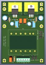
Soldering
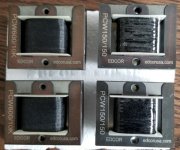
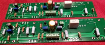
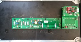
Finally, all components have been received. Specially, Edcor transformers are here. The order was put on July 14. It took a long while.
The Edcor transformer ordered for the voltage stage is PCW Series - 1/2W balanced 150:150.
The 600:10K ones are for other job.
Finally, all components have been received. Specially, Edcor transformers are here. The order was put on July 14. It took a long while.
The Edcor transformer ordered for the voltage stage is PCW Series - 1/2W balanced 150:150.
The 600:10K ones are for other job.
Attachments


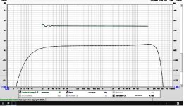
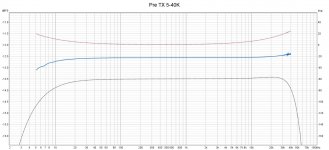
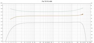
Frequency Response of the voltage stage without transformer
Using Focus rite scarlett solo USB and REW.
L and R channel 20-20K Hz +/- 0.1db, very good, measured with 150 ohms load.
Using Focus rite scarlett solo USB and REW.
L and R channel 20-20K Hz +/- 0.1db, very good, measured with 150 ohms load.
Attachments
Last edited:
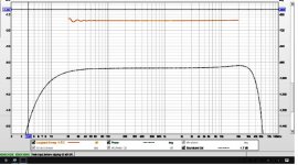
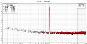
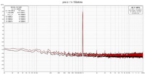
THD+N
It is expected. The voltage stage with audio IC and buffer will have excellent number.
the purpose of the test is just to confirm flawless PCB design and components layout.
L channel at 150 ohms load, THD+N 0.00075% at 1Vrms, 0.0035% at 8.15Vrms output, DC offset 5.5mV.
R channel at 150 ohms load, THD+N 0.0011% at 1Vrms, 0.0066% at 8.1Vrms output, DC offset 6.5mV.
Attachments

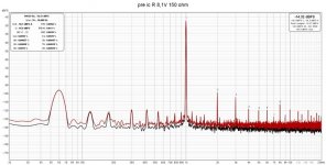
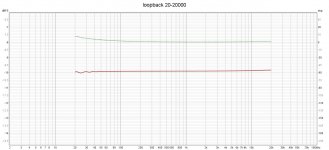
Corrected number:
L channel at 150 ohms load, THD+N 0.0083% at 1Vrms, 0.014% at 8.15Vrms output, DC offset 5.5mV.
R channel at 150 ohms load, THD+N 0.0079% at 1Vrms, 0.011% at 8.1Vrms output, DC offset 6.5mV.
L channel at 150 ohms load, THD+N 0.0083% at 1Vrms, 0.014% at 8.15Vrms output, DC offset 5.5mV.
R channel at 150 ohms load, THD+N 0.0079% at 1Vrms, 0.011% at 8.1Vrms output, DC offset 6.5mV.
- Home
- Amplifiers
- Pass Labs
- LD1014D Id-Vds-Vgs Curve