Congrats Yander26!!! and thanks for the feedback once again.
(Uhoh, just read your second reply.... hope its ok with movies)
I am thinking I may go this route since I would like to have the most out of the ATI AllinWonder.
Just starting out with the basic OHP and this would get it started in the right direction at least.
Boxing it up can be a second challenge / project for me.
I appreciate you taking the time to measure that out too.
Oh, you mentioned you put the fresnel on the glass, pardon my confusion here, but are you talking
about the fresnel of the OHP or do you have another fresnel with this setup? (Once again, I read your
last posts but dont recall ) Just trying to mentally put this all together and get a good visual of it.
video card ---> Kogi LCD ---> ontop of OHP stage ---> 350w halogen projecting through to top lens...?
Hey remp:
BellMicro never called back. Figured that due to holiday. Will see if they due actually call Monday. If not I will try them again.
Thanks !
DragonzTeeth
Yander26
Sorry you still got that optics problem. Just a suggestion remember when you did some soldering to separate the boards and I think I remember you saying some were grounds. Well its possible it does need all the grounds.
Connor. Welcome
I am looking at how we can help.
Sorry you still got that optics problem. Just a suggestion remember when you did some soldering to separate the boards and I think I remember you saying some were grounds. Well its possible it does need all the grounds.
Connor. Welcome
I am looking at how we can help.
Looks good with video
Ok, I just tested this setup with my tv tuner card, and with a DVD I am happy to say it looks great. With video you can't tell that the top is darker, although if your looking for it with solid blue colors you can see it. As for the connections, I was wondering if that might have something to do with it, but I doubt it, but its worth a check. There were 8 connections needed, I used 9 to ensure the ground. The wires I used are a bit longer than really needed, but I would be surprised if that was the problem. As for the fresnel lense, that is the lense that is from the overhead. I am quite happy with it so far, my friend has a manufactured projector and his is much lower resolution and not as bright as what I have, so he is jealous. Now to put this all in some sort of box, so I can hang it from my ceiling.
Ok, I just tested this setup with my tv tuner card, and with a DVD I am happy to say it looks great. With video you can't tell that the top is darker, although if your looking for it with solid blue colors you can see it. As for the connections, I was wondering if that might have something to do with it, but I doubt it, but its worth a check. There were 8 connections needed, I used 9 to ensure the ground. The wires I used are a bit longer than really needed, but I would be surprised if that was the problem. As for the fresnel lense, that is the lense that is from the overhead. I am quite happy with it so far, my friend has a manufactured projector and his is much lower resolution and not as bright as what I have, so he is jealous. Now to put this all in some sort of box, so I can hang it from my ceiling.
Lemming, Connors
We are not into motherboards here. What we are looking for is a SIMPLE solution to connecting a cheap Laptop LCD which many were LVDS and newer units still are, to a driving source either a PC or a stand alone board.
Reason for not going the Motherboard route is BIOS needed to control LVDS laptop Screens would have been in the original Laptop and probably known only to the Laptop manufacturer.
Therefore likely to be hard to find/duplicate. Also a lot of guys already have a good hometheatre setup with good video cards and probably not interested in changing to another MB at present
So far after bypassing all the death merchants both here and at EIO.com who say its too hard, its impossible, it won't work, we are wasting our time etc etc we have achieved a measure of succes by finding Spectrah.com who offer video cards and stand alone cards with good specifications particularly their ARV-468 which takes in DVI, VGA, S-video and composite video and puts out LVDS and TTL. The major plus with these units are they have their own setup BIOS on the boards catering for a variety of screen sizes/resolutions. We have also found the DICON range of stand alone cards with 16 BIOS settings but only takes in VGA.
The LVDS is a simple concept using just 3 cable pairs to transmit 24 bit colour to high resolution screens plus a clock pair, and started off with a 20 pin Hirose connector. I have noticed that as transmitting distances got longer and longer more variants of the LVDS system cropped up eg LVDS 01, 02, 03. Also 30 pin and 40 pin connectors are now being used.
I am pushing this Laptop LCD LVDS idea because I think it is a way to obtain cheap LCD screens but others here are finding alternative methods of getting inexpensive good quality screens operating eg Yander26 has described his solution using a VGA monitor giving him a good 1024 x 768 resolution large screen projector for not a lot of money.
Whatever works is good. Thats about all I can help you with unless someone else has some thoughts.
Anyway best of luck with your projects.
Remp
Thanks to you and all the others for helping me understand all this. Its been real helpful and best of luck with your projects. If there's a breakthrough we'll let you know -- always useful cros-fertilisation of ideas!
Thanks to you and all the others for helping me understand all this. Its been real helpful and best of luck with your projects. If there's a breakthrough we'll let you know -- always useful cros-fertilisation of ideas!
What is the difference between TTL and LVDS as applicable to driving an LCD screen.
One of the things to grasp is that LCD screns demand very high amounts of data to create a moving picture. Very high means extremely high amounts.
There are some compresion systems which send you one frame of a picture, which is drawn on the screen and you see an image. Then if the picture changes they only send you the parts that have changed. This is to reduce the huge amount of continous picture data down to a much lower amount of data. Thats fine except this compression technology is imperfect. So you can see jaggies. Not a smooth high quality picture. It will improve as technology marches forward.
All the better LCD driving systems send you all the picture information all the time even if nothing is moving on screen, so there is a continual large amount of picture data tranfered from controller to LCD all the time. And it looks good.
How do they do it.
As you know there are 3 primary colours in a CRT and a LCD. Red, Green and blue.
If they only sent you the blue picture data you would get a blue screen. It could be light blue, mid blue or any one of a number of shades of blue. Same with red and green. But by sending some red and some green and some blue you get any one out of 16 million colours to colour a pixel. So that pixel right in the center of the screen could be any colour picked from a pallete of 16 million colours.
Sounds like a lot of colours. Sounds like a lot of wires.
Fortunatley there is a simple way.
Inside a digital computer things run on BYTES. One byte is composed of 8 bits. Any of the bits can be on or off.
If all the bits are off the result is zero.
If all the bits are on the result is 255.
The range between 0 and 255 is 256.
So now we can have a red BYTE with 8 red bits that can give us any value in the range of 0 to 255.
Thats good. We can now get 256 values of red ranging from no red to full red
Before bringing in the green and blue lets make a controller to handle the red. We need 8 controllers. one attached to each red bit. This is were the TTL comes in. At the computer end we load the 8 controllers with the red value for a given pixel location. lets say 255. All controllers are on. We send it via 8 wires to the LCD and at the LCD location the LCD decodes the information on the 8 wires and says to itself they are sending me 255 for red , I am now at pixel number 100 or whatever so I will turn on the red part of the pixel full. Thats it. You see a full red pixel at pixel location number 100.
Exactly what is supposed to happen. By now the LCD row/coloumn drivers have moved on to pixel location number 101 and the whole scenario is repeated.
TTL then is a mini controller for each of the 8 red colour bits, for each of the green colour bits and for each of the blue colour bits.
That makes 24 minicontrollers and 24 wires from Video card to LCD. 24 wires. Those 24 wires may be 3 meters long. There is a lot of noisy radiation from such a cable. The longer the wires the more radiated noise.
The FCC have very strict regulations regarding radiated noise from computers so the options are a very heavily sheilded connecting cable or a means to send the TTL signals from the controller to the LCD without making any noise.
Next page tomorrow.
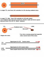
LVDS (low voltage differetial signalling) is one of the many ideas thought up to reduce the noise radiated from TTL wires.
In addition to reducing radiated noise by a large factor, LVDS takes the 40 wire TTL signals and instead of transmitting them all in parallel changes them into serial form ie one TTL signal after the other.
This is doen at very high speed, sent down the cable link from controller to LCD and at the LCD end decoded back into regular TTL signals.
In the process 30 - 40 TTL wires are reduced to a much smaller number of wires.
Advantages
Reduced radiated noise
Much smaller number of wires
Not needing double or triple sheilded wires
Can run on unsheilded twisted pairs.
Long distance/short distance
Useful for other devices eg SCSII hard drives
Disadvantages
Additional cost of LVDS transmitter
Additional cost of LVDS receiver although if the panel has it built in no extra cost.
See drawing
Attachments
Speed
Now we come to a very important part of the whole deal about TTL and LVDS.
In part one I indicated huge amounts of data are being sent from the controller to the LCD. As LCD's get more resolution more data is required.
Just to give you an idea take a 1024 x 768 LCD panel.
Good resolution. Nice picture.
1024 x 768 gives 786432 pixels.
But each pixel is red green and blue so we actaully need
786432 x 3 = 2,359,296 picture data
But hold on.
The picture is redrawn anywhere between 60 and 100 times a second.
So at a high refresh rate of 100 times a second we need
2359296 x 100 = 235,929,600
Thats 235 million picture data's per second. Every jolly second that data comes down from the LCD controller to the LCD.
PHEW.
And thats just for a modest 1024 x 768 LCD screen
You can imaging how much data is needed every second for a 1280 x 1024 screen.
Now here is the problem
TTL operates between zero volts = bit off and +5 volts = bit on.
0-5v
In electronics zero volts to 5 volts can take an appreciable amount of time to get from 0 to 5 or from 5 back to 0. Its called the transition time.
The reason for the wide range from off to on is noise. In a noiseless world you could have virtually any difference to signal a bit is on or a bit is off.
For example
0v = off
1v = on
Another example
0 = off
0.0000000001 = on.
In a noiseless circuit the electronic could easily figure out that 0.0000000001 is different from 0 so it could give the correct answers and it would be quite quick moving from 0v to 0,0000000001v
But its not possible at normal temperature.
Noise interfers and thus to make it dead certain that the circuit is signalling on or off regardless of noise they go for the range 0v = off, 5v = on.
So the wide transition from 0 to 5v gives high noise immunity but slows the circuit and ironically causes much noise itself.
Big problem.
How do you get high speed data transfer without causing a lot of noise
The answer is surprisingly simple.
Instead of using a single ended solution,..... use a balanced method where equeal but opposite radiated noise cancels out, and instead of using 0 to 5v, use a much lower voltage swing like 300millivolts on the grounds that the noise is gone.
First get rid of the interfering noise, then lower the voltage swings.
Circuit gets much faster, consumes less power and reduces its own radiated noise.
So we now have a very very fast method of moving data from A to B. How do we use it.
Again its relatively simple. Just get the LVDS transmitter to look at the TTL data, Collect the first piece of data, send that, collect the second piece of data, send that and so on. All happening at millions of pieces of data per second.
The TTL will work by itself but as panels have improved TTL needs assistance at high data transmision rates and distances over a few meters. LVDS assists the TTL signals get to the LCD faster using less power, making less radiated noise and preserving the quality of the data.
This is a simplified attempt to show how TTL and LVDS function together.
There are other ways to do the same or a similar job but if its digital you want, high speed transmission is an absolute must. Otherwise no picture.
********************
How this ties in with LCD panels is like this.
I believe there are thousands of good laptop LCD's available cheap. I think many of them have an LVDS receiver already built in.
If you are going to use a computer for projection you will already have a video card. Possibly a very good one.
As you know your video card is all digital until finally it converts digital signals into analogue signals that leave the video card via the DB15 VGA connector. Just before the D/A takes place some of your video cards may have a 40 - 60 pin TTL header. Plug in a small low cost TTL to LVDS transmitter board, send the signal to your Laptop LCD where it plugs into the built in LVDS receiver connector and there you are. Job done.
Life is not as simple as that but it could be. All we have to do is gain some more solid information on TTL, LVDS, DVI. Video cards and what if anything is most commonly fitted on the back of an LCD as a connector.
It's like someone asking you for a drill bit. You say "what size". They say," does it matter". It does matter.
Just a fraction more knowledge and things start to look less complicated.
Good postings Remp!
Going to bed a little less stupid tonight for sure! 🙂 Also glad that I ordered a couple of extra cables for my spectra 😉
So far the list from spectra is as follows:
LD S270M video card
L-Cable- J32060
V-Cable- 33160
The L cable is for the panel I hope to find... NL10276AC30-04 at a price I can afford.
The V cable is for a LQ10D42 which I have found localy and can afford. Cables are actually prety cheap the 60cm flavour is only about $15 US/each I have no idea how well the backlights will come off of either of these units, so I just might trash some gear before I'm done ~L~
If anyone knows where I can find one of the following panels or can coment as to which is best, I'll buy the appropriate cable and give it a try.
LVDS Panel support
LG LP121S3
Chi-Mei N141X201
NEC NL10276AC30-04
10.4 inch LCD Panel
NEC NL6448AC33-18
Sharp LQ10D42
LG 104V2
12.1 inch LCD Panel
Sharp LQ121S1DG11, LQ12S41, LQ12S31
NEC NL8060AC31-12
LG LB121S1
ADI AA121SK02
Torisan TM121SV-02L01
Toshiba LTM12C275A
15 inch LCD Panel
Sharp LQ150X1DG11
Samsung LT150X1-151
Toshiba LTM15C151A
LG LM151X2
A little off topic here... but any thoughts on a Delta3 for the projection lens? I have 3 of them off a DOA crt pj.
zardoz
Zardoz
I understand lens from CRT projectors are no use for projectors because they were designed to work with the curved face of the CRT tubes. No sure about this. Someone else will know.
For anyone interested in how 8 bits can count from 0 to 255 the attached zip file contains an .exe file that shows how it's done.
Its a very simple no frills program that runs under MSDOS but will also run in a dos box.
Attachments
Here is a link to Tom's Hardware site.
This page describes how to identify the 3 most common Digital panel connections available for the present and what will happen in the future.
http://www4.tomshardware.com/display/99q3/990707/tft-3-03.html
This page describes how to identify the 3 most common Digital panel connections available for the present and what will happen in the future.
http://www4.tomshardware.com/display/99q3/990707/tft-3-03.html
airplanes are wonderfull things...
my spectra card left Taiwan this AM it's in Montreal now for customs clearing....just 2 lousy provinces away. Those customs guys better be nice to my new toy ~G~
now the wait is on for the panel from the US, I've got my lamp and ballast, possible reflector and a whole whack of len's from the dead CRT. the CRT lens pack only has one glass element in each 4.5 inch across approximately 18 inch focal point ( very non scientific test was used )
zardoz
my electronics missed their flight...
Apparently it was only the customs papers that had arrived in Montreal (for pre-clearance from customs). Coming form Taiwan it goes to anchorage for sorting then to memphis to fedex's "super depot" where it missed it's flight. If it were'nt for the fact that it's a video card I'd swear it missed the flight cuz it was drinkin in the airport bar...LOL The upshot is that it was fedex's fault that it missed it's flight, soooo.. it looks like all I'm going to have to pay is the duty and taxes, the freight from Taiwan is going to be free for me ~S~
zardoz
Zardoz has opened a thread about a useful piece of equipment and with his permision I have reposted the link here.
http://store.viewsonic.com/html/ibe...0008&item=40866&JServSessionIdroot=z87h1qw8dw
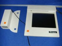
This is a desktop LCD controller from Viewsonic. The model number is VB50HRTV and is priced on Viewsonics online store at $99 USD.
It could be useful for those who have or will be purchasing an analogue input LCD monitor for conversion to projection use, but who do not want to tie up a computer to drive the panel.
It has inputs for S-Video, composite Video, DVD, Computer input and has a built in TV tuner. Output is standard VGA analogue output and can drive a number of resolutions at several refresh rates.
It also includes a remote and connecting cables.
http://store.viewsonic.com/html/ibe...0008&item=40866&JServSessionIdroot=z87h1qw8dw
This is a desktop LCD controller from Viewsonic. The model number is VB50HRTV and is priced on Viewsonics online store at $99 USD.
It could be useful for those who have or will be purchasing an analogue input LCD monitor for conversion to projection use, but who do not want to tie up a computer to drive the panel.
It has inputs for S-Video, composite Video, DVD, Computer input and has a built in TV tuner. Output is standard VGA analogue output and can drive a number of resolutions at several refresh rates.
It also includes a remote and connecting cables.
Re: Montreal
hey hey!!! 😉 i'm from montreal...
je comprends pas!!!
bah... hehe
uvodee said:You never know,
those French speaking guys.....
Jean-Pierre
hey hey!!! 😉 i'm from montreal...
je comprends pas!!!
bah... hehe
shopping
I bought a bunch of stuff today for the project.
1: beatup old elmo OHP HP-L14 it's army surplus (literaly just like me cost) $10.00cdn (cept I'm costing them bunches more in pensions) The frezi is a dissapointment (plastic) and it seems to be slightly convex on the "this side towards lamp" side. Does anyone know if this is a flaw? or intentional in anticipation of the heat of the lamp housing causeing some sag durring a long projection? Also the head on the OHP is intact but looks kinda cheap on the optics for what I'm wanting.
2: I bought an 18 inch SST bowl it's 6 inchs deep $20.00cdn it GLEAMS. However it has a flat bottom, my thoughts are to punch a hole in the bottom large enough to accept the stem and part of the taper of my MH HID 400 watter. This puts the "envelope" (where the really bright light is made) at from what I can see is the ....(uh for lack of complete understanding) optical centre? What I mean to say is that at this level of object insertion into the reflector this is where the object appears perfectly magnified.... by a BUNCH of times. So my reflector/lamp would be like this (- with the end of the envelope pointing at my screen....the length then being exposed to this (holy cow is it shiny!) reflector.
If the big shiny bowl is not a good plan folks tell me... I will give it to my wife for bread making. What I mean is... if I'm just swamped with the info I have absorbed in the last few weeks and am at overload set me straight please. (remp, I know you will and I thank you for that) I've got focal legth and angle of incidence calcs just drowning my brain right now (elliptical! NO!! spherical!! No No No octododecahedral!!!!!!! < does that exist? LOL)
I got info on lowE glass a panel anywhere from the size of a 12 inch LCD to 2 feet square (apparently at this size it 's all the same) roughly $25.00. A triple glazed lowE roughly $50.00. I gotta tell ya something....the triple glazed lowE was cool to the touch compared to the double which was warm, light quality was affected in a minor way by the triple (like a ....uh.. neutral filter?)
No commitment on this aspect yet from me... any thoughts?
Made friends with the local lighting guy....that was an education! Once I started to explain what I was doing and how I hoped to achieve it he got this "all of a sudden I have a prety good idea how this is supposed to work" look on his face. Then he was ready to offer lot's more help. The little tube MH HID's (more point source?) burn out prety often according to him. At very low hours by comparison to the mondo big bulbs 3,000 hours VS 10,000 hours. Heat differance is negligable between the two at same wattages. Colour however can more easily be found in the tube style.. that is more ranges of kelvin. The big 400 MH that I have will work if the outer skin is missing, but they produce BIG UVee's without this treated skin.
He was concerned about the colour degradation over time of the big overhead bay lamps, I explained I might be able to compensate that a little with gamma on the computer that controlls the image, now if it works .. he wants one. He's the second guy LOL
The first was a guy with a bunch of LCD's from high end laptops (not on my list as tested to work with, but simmilar... he's willing to let me come to his shop and try panels with same pinouts if this proves to be do-able) .
I have the optics scrounged from the dead LBL CRT looks like I have three of each...duh.. how'd that happen ~L~
1: goofy looking lens(plastic) that sits next to the CRT, looks useless for me.. but will keep till I know
2: plastic lens about 4.25 inchs unknown fl (gives a fisheye look) 3: real prety 4.5 inch glass lens fl I'm thinking about 18 inch fl
4: a plastic 5.5 inch "outer" lens (usefullness? unknown)
The card should be here on monday.. the LCD.....geez I hope next week.. an in first class condition...fingers are crossed. I've heard they sometimes dont make the border crossing very well.
Feed back requested please, this is a project in constant flux at the moment.
zardoz
kodak datview ??? is it dataview?
Yassasin! Yassasin
DATAVÝEW C181 800x600 Pix.
DATAVÝEW C191 1024x768 Pix.
DATAVÝEW E221 1024x768 Pix.
DATAVÝEW M320 1024x768 Pix.
DATAVÝEW 960 1024x768 Pix.
i could not find anything else through a internet search ....
what is the production date of the panel and can you post here ALL the info that you can read on the production tag please ?
dank U wel,
gracias,
merci beaucoup
danke zehr
enne schol!
Re: Kodak Pannels
There's no point in getting annoyed. Most likely the reason no one has answered your post is because quite possibly there is no one here that has had any experience with that panel. I didnt even know Kodak made a panel. If you want I'll tell you it will work first rate....but I have no idea. So cant offer an opinion. Why dont you post it's specs such as resolution, inputs and the like. Then we as a group may be able to "theorize" how it could/should work for you.
Have you tried the "Good panel Bad panel" thread?
zardoz
getem56 said:As no one seems to be answering my questions i am getting really annoyed.
Can I Use A Kodak Datview Pannel For Projection Or has it got the wrong colurs like vga or somthing please help
There's no point in getting annoyed. Most likely the reason no one has answered your post is because quite possibly there is no one here that has had any experience with that panel. I didnt even know Kodak made a panel. If you want I'll tell you it will work first rate....but I have no idea. So cant offer an opinion. Why dont you post it's specs such as resolution, inputs and the like. Then we as a group may be able to "theorize" how it could/should work for you.
Have you tried the "Good panel Bad panel" thread?
zardoz
- Status
- Not open for further replies.