I can probably find it in the thread. But I have to multiply with the transformer relation. Higher gain = higher Rout.
I don't need much gain. x2 or x4 gain. Probably x2 with balanced out.
I don't need much gain. x2 or x4 gain. Probably x2 with balanced out.
I found this answer in kit thread:
Iron Pre SE is having settable gain +6db or +12db; that's 2V/V and 4V/V; in first case Rout is 2^2*Rout of JFet buffer, in second case it is 4^2*Rout of JFet buffer
Iron Pre Bal is having strictly just +6db of gain, which is 2V/V; Rout is 2^2*Rout of JFet buffer, per phase; or 2*(2^2*Rout of JFet buffer) sum/balanced
Rout of complementary JFet buffer is Rout of Nchannel side in parallel with Rout of Pchannel side
that being (1/xconductance + Rsource) of upper, in paralell with (1/xconductance + Rsource) of lower
Rsource roughly 1/2 of common trimpot in sources ; 10R to 20R trimpot
xconductance of tiny TO92 Toshiba critters is (taken midrangey) 15mS ......... you can see it as ~65R resistor (1/S)
so, 65R + 10R up, 65R + 10R down, means 75R up and 75R down, means 37R5
easypeasy
I assume that Rout is "low enough" 🙂 ......lower than a typical tube pre which is about 600 ohm 🙂
Maybe this is the Iron pre buffer........is the original Iron Pre thread the "kiss boy thread"?

A got more feedback from Connex regarding how to measure with scope probe. I may do this some time using a cheap probe:
"The 100Hz noise is most likely common mode noise caused by the currents which are flowing through earth connection of both the SMPS and oscilloscope.
When measuring the noise try to use the probe with very short wires of the same length soldered directly to the tip. Maybe it is not convenient to sacrifice a good probe by soldering onto it directly but you can try to wrap some wire around the tip and barrel without soldering.
Also add a ferrite core used for EMI filtering. This helps with CM noise and the overall noise will be lower."

Apart from this I am in a process in preparing to put the two SMPS modules into its own chassis.
22 mF caps has arrived and 10 mH 5A chokes are in transit. I am quite sure my two 2U Galaxy chassis will work.
With 160 mOhm DC resistance in choke and the power wire the filter is more like a RLC filter........I think.
I can re-adjust voltage at amp to 65V so adjustments I already did (bias and DC-level) still works. But I will check of course.......when time comes.
"The 100Hz noise is most likely common mode noise caused by the currents which are flowing through earth connection of both the SMPS and oscilloscope.
When measuring the noise try to use the probe with very short wires of the same length soldered directly to the tip. Maybe it is not convenient to sacrifice a good probe by soldering onto it directly but you can try to wrap some wire around the tip and barrel without soldering.
Also add a ferrite core used for EMI filtering. This helps with CM noise and the overall noise will be lower."
Apart from this I am in a process in preparing to put the two SMPS modules into its own chassis.
22 mF caps has arrived and 10 mH 5A chokes are in transit. I am quite sure my two 2U Galaxy chassis will work.
With 160 mOhm DC resistance in choke and the power wire the filter is more like a RLC filter........I think.
I can re-adjust voltage at amp to 65V so adjustments I already did (bias and DC-level) still works. But I will check of course.......when time comes.

Yes!
Of course!
I have already started the preparing for moving the SMPS's from amp chassis to two small Galaxy chassis.......so amps are not in a mode where they can play music 🙂 VFET amp is back in business.........as a "spare amp" it is ok!
I have received the 22 mF caps and the two 10mH 159ZJ Hammond's for the amp chassis LC filters.
I will continue the work step by step.......but will take some time.....go get finished......
I feel confident that the amps will end up being "super silent".
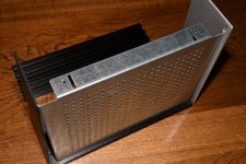
I am looking at how to mount the SMPS in the two Galaxy chassis I already have.
It is first time I have a base plate for these.
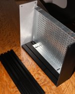
I intend to mount the base plates as showed in pictures below. This is the only way that makes sense to me. Then I have as much room inside the chassis as possible but still has space for screw heads "below" base plate so bottom plate can be attached. The question is if this was the intended way? .....maybe I have overlooked something?
This way the sidepanel will have the "ugly" side outwards but both sides have same kind of finish so I assume they were designed to have either side outwards?
The "ugly" side has the rail for 3mm nuts at horizontal center so this would leave me less space inside the chassis if base late was mounted that way (even if the "long slide holes" where used in base plate for mounting (I think).
It is first time I have a base plate for these.
I intend to mount the base plates as showed in pictures below. This is the only way that makes sense to me. Then I have as much room inside the chassis as possible but still has space for screw heads "below" base plate so bottom plate can be attached. The question is if this was the intended way? .....maybe I have overlooked something?
This way the sidepanel will have the "ugly" side outwards but both sides have same kind of finish so I assume they were designed to have either side outwards?
The "ugly" side has the rail for 3mm nuts at horizontal center so this would leave me less space inside the chassis if base late was mounted that way (even if the "long slide holes" where used in base plate for mounting (I think).
Attachments
yeah, that's the way
what I'm routinely doing is - drilling 4 new 3.2mm holes on base plate sides , 5mm lower than original ones
that way I'm gaining 5mm more clearance under the base plate, so all mains cables can easily go between base plate and bottom cover
not important in your specific case, but worth mentioning, with base plate in regular amp or preamp
Ok, that sounds like a good idea.
I will continue the assembly and see how the SMPS module can be mounted. Hope it can be done on front plate.
The square holes are probably there to be able to adjust the positions of base plate for more or less clearance but better to have fixed holes which makes assembly easier.
I will continue the assembly and see how the SMPS module can be mounted. Hope it can be done on front plate.
The square holes are probably there to be able to adjust the positions of base plate for more or less clearance but better to have fixed holes which makes assembly easier.
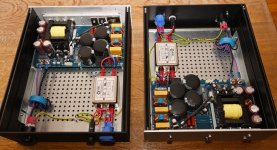
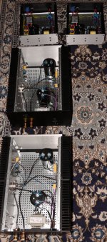
A little progress. The two PSU's are almost ready. The two SMPS's are built into two Galaxy chassis.
I made a small test that they still works. I use Neutrik SpeakOn connectors for the DC-out.
It was recommended by Connex to use AC noise filter and a ferrite core for DC wires. So I added that.
The AC filter is a 10A type and ferrite core is MnZn material. It is called N30 ferrite. As far as I could see it should do its job below 5 MHz. But I am far from a "ferrite expert"!
Next step is to work on the amp chassis to implement the LC-filter etc.
Attachments

That is looking _really_nice!
Yea, i am also wondering about them ferrite HF- noice filtering solutions. Wich are really the best in what application, and how many turns is the ”right” amount with the toroidal core?
My favourite Knipex included for scale.
🙂👍

Yea, i am also wondering about them ferrite HF- noice filtering solutions. Wich are really the best in what application, and how many turns is the ”right” amount with the toroidal core?
My favourite Knipex included for scale.
🙂👍
Connex writes this in their documentation:

So 2-4 turns using 25-33mm diamenter ferrite core. I used 4 turns.
I think the long ferrite core you have on picture if you just pass through the wire(s) it counts as 1 turn (like the ones you can "click-on" outside a wire).
For this application I read the documentation that wires should just follow each other (e.g. not like a common mode choke).
My favorite Cu wire cutter is a Lindström with white handles. I have a couple of the vintage ones from when they where "Made in Sweden" 🙂
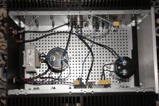
LC filters have now been implemented in amp chassis + other smaller modifications.
Next step is to make the power-wires between PSU chassis and amp chassis.
I wonder what is good practice? .....max. length, shielded vs. unshielded etc.
I have some rubber insulated 3-wire 1.5mm2 cable (unshielded). It is nice and flexible. Plan is to make 1m in length for practical purpose. Then PSU chassis can then be at a distance from amp chassis. As DC-choke has 160 mOhm DC resistance I see no real benefit using e.g. 2.5 m2 for power wire as it will not reduce total R much. The 22mF capacitor will make the low impedance the amp look into. Filter will be more like a RLC filter.
When cables are made I will do some point-to-point measurements from PSU to amp before power comes on to ensure I have not done some very stupid.
Attachments
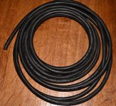

The only purpose for using shielded DC power cable would be to avoid AC-noise to enter the DC-cable. But I guess it will be hard as it is quite low impedance. And then a shield is more to reject RF than low freq magnetic fields. If I don't let the DC cable run along mains AC cables I guess I am fine using the unshielded cable in picture above. The DC-cable will have a small about of 100 kHz ripple (max. 100 mVpp or so).......it could radiate a little. In the old days 100 kHz was "Long wave RF"? .....so will the cable act as a long wave transmitter antenna (without shield)?
Maybe I should look for some shielded cable and then maybe only connect shield to chassis in one end? .....at PSU end?
Maybe I should look for some shielded cable and then maybe only connect shield to chassis in one end? .....at PSU end?
it's enough to shield it just in amp case
don't forget to put amp case on GND potential
or, to avoid problems if cases ever touch - put amp case on safety gnd, having usual blingie between safety gnd and audio gnd situated where it most suits you
don't forget to put amp case on GND potential
or, to avoid problems if cases ever touch - put amp case on safety gnd, having usual blingie between safety gnd and audio gnd situated where it most suits you
- Home
- Amplifiers
- Pass Labs
- Lazy Singing Bush mono block build using THF51s