AFAIK, the hole is hard coded into all the programs I've ever used. You might be able to create a custom "component" pad, with a routed odd shaped hole, just as people do interiour cutouts. It would just be a cutout surrounded with copper, or you might be able to directly edit the final Gerber file with a a text editor, but I don't think anybody has made this easy!
pinkmouse said:
As for the printing issue in Eagle, I use the CAM processor to output EPS, then import them to Photoshop to array multiple boards, move them around the paper, etc, and I have no issues at all with quality. I'm sure other graphics manipulation packages can do the same, I am just familiar with PS.
This is the method that should be used. It's funny to see people trying to print the screen instead... 😀😀😀
I use the old Eagle 3.55 and its CAM processor produces erratic EPS sometimes, but the CAM processor included in the newer 4.x can load older boards and produce nice EPS files.
In Photoshop you can "expand" the copper surfaces to compensate for "contraction" during printing, developing and specially etching. Use the magic wand to select all the copper zones (it works on a particular color). Then go to Select -> Modify -> Expand. Two pixels is usually ok at 600 dpi. Then go to Edit -> Fill, select foreground color and it's done 😀
Workhorse said:Hello Hugh
I know one can change the shape of the pad to anything, but i want to change the shape of the hole of the pad.
regards,
Kanwar
I'd create pads with rectangular or square shaped holes severally with the software. It's just like when you create a new library model for a part, say a semiconductor.
Doc Nordic have developed himself a lot, have learned a lot!
And despite hard figths we had... and because of our disagreements, he developed a even better ideas...by himself and some because of some pressure i have made.
His work now a days is much better compared to the past.
Now, when i watch his products, i do not remember, as i used to remember in the past... always, the wonderfull things Jand Dupont and Jens Rasmussen use to make related boards,
I think they are the best ones!....but.... Nico is going to have that same quality in a matter of more 2 or 3 boards designs.
He made several.... we figth and something results... at least another model.... with swet and some tears...but we go progressing...or.... in the reality, he goes progressing.
The best reference, i have, as boards made with quality into the layout are Jan Dupont boards.... i feel those ones he made, many years advanced compared to others.
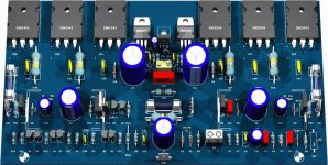
I am very proud.... very proud of my nephew, proud to present you the final Dx Precision I (One) board.
Also my dear friend Hugh, and also others, are very good..but Hugh has that transistor...hehehe... i do not like that one over the other... sex between transistors, in public...not good... also he use to put them misaligned and the wires flying to the boards are terrible!.... well...nothing perfect in this life...we are not perfect too and everything is a matter of personal taste.
Ahahahahah!
regards,
Carlos
And despite hard figths we had... and because of our disagreements, he developed a even better ideas...by himself and some because of some pressure i have made.
His work now a days is much better compared to the past.
Now, when i watch his products, i do not remember, as i used to remember in the past... always, the wonderfull things Jand Dupont and Jens Rasmussen use to make related boards,
I think they are the best ones!....but.... Nico is going to have that same quality in a matter of more 2 or 3 boards designs.
He made several.... we figth and something results... at least another model.... with swet and some tears...but we go progressing...or.... in the reality, he goes progressing.
The best reference, i have, as boards made with quality into the layout are Jan Dupont boards.... i feel those ones he made, many years advanced compared to others.
I am very proud.... very proud of my nephew, proud to present you the final Dx Precision I (One) board.
Also my dear friend Hugh, and also others, are very good..but Hugh has that transistor...hehehe... i do not like that one over the other... sex between transistors, in public...not good... also he use to put them misaligned and the wires flying to the boards are terrible!.... well...nothing perfect in this life...we are not perfect too and everything is a matter of personal taste.
Ahahahahah!
regards,
Carlos
Attachments
Sorry if I missed the point, but why do you need a pad with non-circular hole? The pad itself is drilled anyway, so any tin you pour into the hole to make it rectangular will make the connection inferior in terms of conductivity (thermal and electrical) as well as of physical strength. All mounting hardware I know is usable with circular holes, so what could your intention be?
All the best, Hannes
All the best, Hannes
Yes.... very happy, satisfied with Sprint Layout.
I just cannot wait to receive full program.... gift from Sakis...
Dx Corporation Greek man.
Sakis Petropoulos.
We had problems...now we are within a better relationship... starting some business together.
Old problems we had to forgive and to march to the future in better bases into the relationship.
Russia not more enemie..... so.... everything changed for better in our world... exception is the global warming.
regards,
Carlos
Carlos,
A tight coupling between transistors prevents thermal runaway and closely controls bias - rather like maintaining harmony and avoiding divorce in a good marriage!!
Besides, at our age, is not sex a good thing to encourage?
You are too prudish, you Brazilians........ (Wow, I never thought I'd ever say that!!)
Cheers,
Hugh
Hello
I have Eagle Lite, the free edition, but I still need to learn to made schematic with it.
Is there any kind of guide for dummy for using Eagle Lite ?
I have also DipTrace, they have a free edition version, it very easy for making schematic but not so easy to made a good pbc layout with a star ground with that freeware.
http://www.diptrace.com/index.php
Bye
Gaetan
Do not let yourself be bothered with that Hugh
Just transistors.... i dislike and hundreds love that construction.
regards,
Carlos
Just transistors.... i dislike and hundreds love that construction.
regards,
Carlos
h_a said:Sorry if I missed the point, but why do you need a pad with non-circular hole? The pad itself is drilled anyway, so any tin you pour into the hole to make it rectangular will make the connection inferior in terms of conductivity (thermal and electrical) as well as of physical strength. All mounting hardware I know is usable with circular holes, so what could your intention be?
All the best, Hannes
There are some odd components like off-board bridge rectifier with rectangular terminals which i wanted to mount in pcb, some other odd components like rocker switches also have finned terminals.............thats why.
Hi Kanwar,
As far as i know Protel DXP does not have option for creating non circular holes.
But Altium Designer supports creation of non circular holes.
Check page 30 in following pdf file
Altium Designer Creating Library Components
Regards
pgbhat
As far as i know Protel DXP does not have option for creating non circular holes.
But Altium Designer supports creation of non circular holes.
Check page 30 in following pdf file
Altium Designer Creating Library Components
Regards
pgbhat
pgbhat said:Hi Kanwar,
As far as i know Protel DXP does not have option for creating non circular holes.
But Altium Designer supports creation of non circular holes.
Check page 30 in following pdf file
Altium Designer Creating Library Components
Regards
pgbhat
Thanx alot!!!
Well, drawing rectangular pads in a layout-package is not the main problem, but the production of these in a board house is.
As already said, rectangular pads are non-standard, so you would need to get them milled and this adds significantly to extra costs (if they do it for a single board at all). But maybe you want to do the boards yourself?
Dould you please post a link to such a part? Thank you!
All the best, Hannes
As already said, rectangular pads are non-standard, so you would need to get them milled and this adds significantly to extra costs (if they do it for a single board at all). But maybe you want to do the boards yourself?
Dould you please post a link to such a part? Thank you!
All the best, Hannes
h_a said:Well, drawing rectangular pads in a layout-package is not the main problem, but the production of these in a board house is.
I am talking about rectangular holes not pads.............
Workhorse said:I have Protel licensed Altium Technologies DXP suite, but it has no option as far as i think, if someone knows how to manipulate the pad shape, please tell.
I`m using Protel DXP 2004 and you just double-click on the pad and the menu pops up. There`s an option where you could choose between round, rectangle and octagonal.
Look at the attached picture.
Cheers!
Borko.
Attachments
Oh, now I see what you wanted... Why not to drill little larger pad hole so the rectangle pin of rectifier could get in.... When you solder it ther`s no difference if the hole is round or rectangle.. Why bother...?
bogdan_borko said:Oh, now I see what you wanted... Why not to drill little larger pad hole so the rectangle pin of rectifier could get in.... When you solder it ther`s no difference if the hole is round or rectangle.. Why bother...?
You want to say that if the terminal measures 8 X 1mm then i should go for at least 8mm hole?????????

- Status
- Not open for further replies.
- Home
- Amplifiers
- Solid State
- Layout and Pcboard software... please friends, suggest me something really simple