It is reasonbly easy to edit the actual package as far has holes and pads are concerned....
Just click open library, select the one with the package, then select the specific component and it will open in a window where it can be modified...
Then in you board view, just run the update command under library to import your changes to existing boards... new boards will automaticaly use the modified components and do not need updateing.
Several of the resitors have too small pads, many won't be able to solder at home reliably... especialy those who do not know about or use flux yet. So i just increased the pad sizes... never to be bothered by it again...
So if you idientify something small that irks you with a package, you can edit it and save it for future use...
Can't say I have ever seen the problem you mention of parts not corresponding... also one must remember that the silkscreen outline is an outline... i.e. if you ask for 16mm capacitor the actual silk may be 17mm, to allow you to see the silkscreen with the part installed.
My opinion... (feel free to disagree)
Eagle's graphic output quality is unacceptable in every respect. The schematic libraries look like they are drawn by intellectually challenged 5 year olds. And the PCB traces and pads are equally embarrassing.
What is it with the poor graphic quality of schematic/PCB software? 😎
Cool looking software: DipTrace looks good on the surface but I haven't really played with it much.
For killer PDF output: Bullzip is hard to beat. http://www.bullzip.com/ And if you need transverse output (landscape PDF from a landscape layout) you can download an Apple LaserWriter PPD from Adobe and install it into BullZip. (cool trick!)
..Todd
I use DoPDF as a printer driver to export PDFs from eagle...
You can simply tick the rotate box in eagle print options to print landscape...
I agree the graphics should scale a bit better, but I guess it will get better as time goes on.
You can simply tick the rotate box in eagle print options to print landscape...
I agree the graphics should scale a bit better, but I guess it will get better as time goes on.
taj said:My opinion... (feel free to disagree)
Eagle's graphic output quality is unacceptable in every respect. The schematic libraries look like they are drawn by intellectually challenged 5 year olds. And the PCB traces and pads are equally embarrassing.
What is it with the poor graphic quality of schematic/PCB software? 😎
Cool looking software: DipTrace looks good on the surface but I haven't really played with it much.
For killer PDF output: Bullzip is hard to beat. http://www.bullzip.com/ And if you need transverse output (landscape PDF from a landscape layout) you can download an Apple LaserWriter PPD from Adobe and install it into BullZip. (cool trick!)
..Todd
I actually agree with most of your comments, but .... Eagle is an engineering tool not a graphics design package. It would be nice if it displayed graphics nicer, but at the moment this is not the case. The production of quality PCBs is the end game here not pretty documentation (unfortunately).
A couple of tips to improve the appearance of Eagle, rebuild all your components, they are not design to look good and are very inconsistent because they have been designed by many people over many years.
The screen display and print output are far inferrior to the quality of the produced boards. To get proper quality print output you need to use the CAM processor and print from the gerber files using a suitable gerber viewer.
regards
Sorry Greg, I was not fully awake, I somehow swapped your name and Graham Maynard's
To translate what greg just said, Eagle records the layouts you make as a series of vectors that can accurately instruct a machine to "print" or even mill the required patterns... what it outputs to the screen is just an interpretation of that... Doing a gerber will quickly show the diffirences...
PS, you don't mabe have a black TO220 horizontal package?
Wouldn't mind your capacitor library either..
Nordic said:Eagle can autoplace partnumbers and values, but only on boards with components that are very seperated as you can not move that text manualy... I preffer to hide value and number layers and manualy type my own silkscreen...
In Eagle you can move component partnumber as well as values if you smash (Eagle command in the columne on the left)component in question first. You can do that for schematics as well as board.
For drilling boards, only carbide circuit board drills will hold up. Unfortunately they're easy to break. Hand held anything is out of the question. I want clean holes dead center on my pads. Ideally, one uses a drill press where the drill comes up from the bottom, and the location is viewed with a microscope and crosshair from the top. That was a bit beyond me, but here's a little drill press with very high sensitivity I put together from some scraps of rosewood, maple, and some mechanical hardware from my junk box (I have a better than average junk box).
Attachments
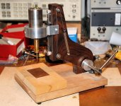
Conrad Hoffman said:That was a bit beyond me, but here's a little drill press with very high sensitivity I put together from some scraps of rosewood, maple, and some mechanical hardware from my junk box (I have a better than average junk box).
Wow. A better than average talent at slapping things together too, Conrad.
Nico & Greg,
Regarding Eagle's output... Thanks for the explanation. I understand why now. However, for us DIY'ers who regularly swap schematics and burn our own boards based on its laser printer output, it's not adequate. Unless we're submitting Gerbers for production, we need proper vector rendering on paper (Eagle, meet Ghostscript) and much nicer schematics. I hope you're right Nico, and they improve upon that aspect in the future.
Greg, you're absolutely right. It does what it's targeted to do, and from what I've seen of production boards, it does it well. But then, the people doing the layouts are pretty talented too. 😉
Sadly, that doesn't cut it for my purposes.
 Maybe I'm too picky in that regard, and I know I'm not their target market.
..Todd
Nordic said:I use DoPDF as a printer driver to export PDFs from eagle...
You can simply tick the rotate box in eagle print options to print landscape...
I tried DoPDF, but it acted really strange and produced odd artifacts, moving objects to strange coordinates (particularly text objects). The rotate output checkbox sounds like a no-brainer doesn't it, but many printer and PDF drivers simply don't, can't or won't do it. DoPDF gets high marks for that.
Bullzip's PDF output is flawless, but it relies on Ghostscript's page formatting routines, which require a PPD (Postscript printer description) file to define any additional page sizes and orientations. Nothing wrong with that really, since that's how real PostScript works, except that all the default/included page formats don't include "transverse" output. 🙄 Anyway, as mentioned, an Apple LaserWriter PPD file solves that problem.
..Todd
Is there any PCB program in which we can
CHANGE THE SHAPE OF THE HOLE OF THE PAD FROM CIRCLE TO RECTANGLE OR ANY OTHER SHAPE....
CHANGE THE SHAPE OF THE HOLE OF THE PAD FROM CIRCLE TO RECTANGLE OR ANY OTHER SHAPE....
Ahhahahahah... i have found one that is able to make copper rounded corners
And this is even better than you squared screws...
ahahahaha.
Kidding, of course..you squared holes are not for screws, as automobile wheels and screws cannot be squared...of course!
regards,
Carlos
And this is even better than you squared screws...
ahahahaha.
Kidding, of course..you squared holes are not for screws, as automobile wheels and screws cannot be squared...of course!
regards,
Carlos
Workhorse said:Is there any PCB program in which we can
CHANGE THE SHAPE OF THE HOLE OF THE PAD FROM CIRCLE TO RECTANGLE OR ANY OTHER SHAPE....
All of them, but you have to go into the part library to do so. I believe Protel can even do so directly on the board, but I haven't worked out how yet. 😉
As for the printing issue in Eagle, I use the CAM processor to output EPS, then import them to Photoshop to array multiple boards, move them around the paper, etc, and I have no issues at all with quality. I'm sure other graphics manipulation packages can do the same, I am just familiar with PS.
I have Protel licensed Altium Technologies DXP suite, but it has no option as far as i think, if someone knows how to manipulate the pad shape, please tell.
Conrad..that's a great drill you've put together. Looks like it's quite accurate and pretty too !

Kanwar,
Protel for Windows 1.12 dated from 1991 will do it directly. Double click or input E (for edit) P (for pad) on the pad, a 'Change Pad Box' comes up, you can change x and y dimensions and octagonal, round or square pads, even do global changes. You can also make it single or multilayered, good for vias.
The program will also do curved tracks, making the artwork quite elegant.
An oldie, but a goody. Carlos tried it, found it difficult to get into (I can relate to that, it's not easy to get started) but it's incredibly flexible. It will run on XP for Windows without problem, can import and export Gerber. You can put the whole program and a reasonable library (you can make your own components) on three 1.44M floppies, but it was originally a dongled program.
Cheers,
Hugh
aparatusonitus said:
In Eagle you can move component partnumber as well as values if you smash (Eagle command in the columne on the left)component in question first. You can do that for schematics as well as board.
You just added a week to my life, and helped me find use for yet another button!!!!!!!!!!!!
Talk about a long learning curve...
To master Eagle, you need to go through the 5 stages of grief!
Denial,
Anger,
Bargaining,
Depression,
Acceptance
I'm confused. You can change the shape of the pad in any of 'em, but not the shape of the hole. Even if you could change the shape of the hole, how would you drill it? Actually, I've seen triangular drills that drill a square hole, but it's not a practical method here. So is the real desire to change the pad or the hole?
What I want is to change the shape of hole of the pad , not the shape of the pad.
I have access to linear slot drills for drilling rectangular or square shaped holes.
I have access to linear slot drills for drilling rectangular or square shaped holes.
- Status
- Not open for further replies.
- Home
- Amplifiers
- Solid State
- Layout and Pcboard software... please friends, suggest me something really simple