For some strange reason, no one wants to build LatFet amps 🙂
I found LATFETs at mouser but they are quite expensive. I have lot of HEXFETs at home.
PCB v3.0 uploaded (KiCAD + missing 3D models)
A lot of tidying has been done.
Re-routed some tracks.
Used inner layers to support high current tracks instead of going 2oz PCBs.
Gerber files included as well.
A lot of tidying has been done.
Re-routed some tracks.
Used inner layers to support high current tracks instead of going 2oz PCBs.
Gerber files included as well.
Attachments

HExFet version details
Since it looks like more people is interesting in building HexFet version, here are few observations regarding this version.
1) Most recent sim file is attached here.
2) The original LatFet amp was tested with op-amp LT1056. It is not confirmed it will
work 'as is' with different op-amps. It might, but no one tried yet.
3) C9/C12 (22pF) might have to be increased to 33pF or even 47pF in actual build. 22pF most likely will work (and the lower value the better), but be prepared to increasing it if you have oscillations.
4) 2SA1381 and 2SC3503 are usually available as KSA1381ESTU and KSC3503DSTU, with different betas:
C: 40 - 80
D: 60 - 120
E: 100 - 200
F: 160 - 320
E and D range overlaps, so for the best results, it's better to test a whole bunch of them, and find matching pairs.
Otherwise - the amp will still work fine, even without matching, but of course Thd/FFT profile will be slightly worse.
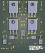
5) With one pair of output devices, source resistors (0.22) are not needed, with 2 pairs - required.
6) All TO-126 transisors need to be cooled (heatsinked)
6) 2SC/2SA transistors are all plastic, so they don't need isolating pads when mounted on the common heatsink.
7) BD139 has metal pad, and needs to be isolated from the heatsink.
Or - it could be mounted upside down, with plastic surface facing heatsink.
Or - it can be replaced by pretty much any NPN transistor(with the same voltage as BD139, or better), preferably all plastic - but in this case R24 may need to be changed/adjusted to allow for proper idle current adjustment. Use sim to find out..
8) C1 preferably should be bipolar. Polar caps have slightly higher distortion.
9) C7 should be bipolar.
10) All small caps should be ceramic X7R C0G
11) IRFP output devices need Zener gate protection. Like in this amp P101 (example). Zeners could be 8V to 12V.
These were omited in the sim file.
Since it looks like more people is interesting in building HexFet version, here are few observations regarding this version.
1) Most recent sim file is attached here.
2) The original LatFet amp was tested with op-amp LT1056. It is not confirmed it will
work 'as is' with different op-amps. It might, but no one tried yet.
3) C9/C12 (22pF) might have to be increased to 33pF or even 47pF in actual build. 22pF most likely will work (and the lower value the better), but be prepared to increasing it if you have oscillations.
4) 2SA1381 and 2SC3503 are usually available as KSA1381ESTU and KSC3503DSTU, with different betas:
C: 40 - 80
D: 60 - 120
E: 100 - 200
F: 160 - 320
E and D range overlaps, so for the best results, it's better to test a whole bunch of them, and find matching pairs.
Otherwise - the amp will still work fine, even without matching, but of course Thd/FFT profile will be slightly worse.
5) With one pair of output devices, source resistors (0.22) are not needed, with 2 pairs - required.
6) All TO-126 transisors need to be cooled (heatsinked)
6) 2SC/2SA transistors are all plastic, so they don't need isolating pads when mounted on the common heatsink.
7) BD139 has metal pad, and needs to be isolated from the heatsink.
Or - it could be mounted upside down, with plastic surface facing heatsink.
Or - it can be replaced by pretty much any NPN transistor(with the same voltage as BD139, or better), preferably all plastic - but in this case R24 may need to be changed/adjusted to allow for proper idle current adjustment. Use sim to find out..
8) C1 preferably should be bipolar. Polar caps have slightly higher distortion.
9) C7 should be bipolar.
10) All small caps should be ceramic X7R C0G
11) IRFP output devices need Zener gate protection. Like in this amp P101 (example). Zeners could be 8V to 12V.
These were omited in the sim file.
Attachments
Last edited:

Any desire to incorporate optocoupler bias for the hexfet version? The kind of bias seen in whammy and m2 amp from the pass forum has many advantages for budget conscious amateurs like me. The build would be cheaper and safer because theres no worry of hexfet thermal runaway.
Donovas, can you provide a link to the amp(s) with this kind of biasing?
I thought this was motly limited to class A amps..
I thought this was motly limited to class A amps..

List of mods:
- C1: Non-Polarized
- C2: Non-Polarized, 1000uF instead of 100uF
- C4, C5: Fixed footprint, now 1210
- C6, C7: 1000uF/25V
- C9, C10, C11, C13, C14: operating voltage should be 100V or more, farnell offers either 50V or 1KV, so I chose 1KV
- C16: 100nF/200V
- R1: 10R\1W dunnu about this, Daniel says if oscillation happens, this resistor fries away..
- R23-26: 33R
- Fixed GND and GNDS connections and which components connect to them.
- A lot of tracks rerouting, really a lot...
Daniel you received those files 23rd of March, I allowed myself two extra days to check tracks and finalize some changes 😉
Daniel, there are 96 Emails titled "Latfet" in my inbox received from you which totals to 192 Emails starting the 7th of March, this was a teamwork not a single person effort, you checked my files like 20~30 times before the PCB design formulated to what it looks like now and physically checked if TL071 works OK or not. 192 Emails sound like a two-months enterprise project!
Changes suggested by Daniel are reflected in this final version, so there will be NO more mods unless someone finds an error.
One of the best pcb layouts I have seen on this site. Really nice work.
Do you consider "SMT Assembly" option of JLCPCB before order? I think most effort will go to smd soldering, (except chassis work of course) if someone decides to solder all parts by hand.
I was actually looking for an original design for complementary bjt pairs of mine (salvaged old Motorola 2N3716/2N3792's) but this design took my attention with @Minek123's other threads.
Last edited:
Is there any merit in converting the circuit to use the non inverted input as the input and how much change is required if not just swapping the opamp pins?
I was a bit confused because it uses the opamp in a non inverting fashion but with the pins swapped. As in the input should be pin 3 if the feedback is be the way it is. I think what i missed is that the signal is inverted somewhere in the discrete stage?
- Home
- Amplifiers
- Solid State
- LatFet Amp Based on Philips AH578