@Minek. First of all thank you for sharing this great project. 

I would like to talk about technical things first, detailed listening impressions will follow.
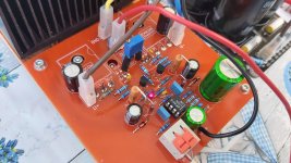
Power supply: 36V -> 300VA toroid, 4x10kuF United Chemicon + 2x10kuF Kemet Slit Foil elkos. Output coil still not installed. Resistors are Yageo 1% 50ppm, Takman Rey and Dale. Elkos are low ESR Panasonic FR and Nichicon Muse BP.
As you recommended I set the quiescent current of the amplifier to 105mA with a 100 ohm trimmer. The trimmer shows 67 ohms. The output offset was 0mV at start-up, I measured it again after an hour of intensive use, the value is 0mV. Maybe the DMM failed? I replaced the battery in it and remeasured again: 0mV. Incredible. The output offset is 0mV in all conditions, ie beyond the measuring limit. I have only selected 2N transistors (Central Semiconductor), they matched to equal hfe: 213. Drivers and fets are not matched. The 150 Ohms, 2K ohms, and heat sinks are moderately warm, as expected, with no special warming issue. The amp is rock stable like the Viktor Orbán's forehead.😀
I experienced only one strange thing. I measure -12.8V on the negative side of the opamp's rail and 13V on the positive side. Why this asymmetry? This is normal? Or could it be the fault of the opamp?
Thanks for the answer.
I would like to talk about technical things first, detailed listening impressions will follow.
Power supply: 36V -> 300VA toroid, 4x10kuF United Chemicon + 2x10kuF Kemet Slit Foil elkos. Output coil still not installed. Resistors are Yageo 1% 50ppm, Takman Rey and Dale. Elkos are low ESR Panasonic FR and Nichicon Muse BP.
As you recommended I set the quiescent current of the amplifier to 105mA with a 100 ohm trimmer. The trimmer shows 67 ohms. The output offset was 0mV at start-up, I measured it again after an hour of intensive use, the value is 0mV. Maybe the DMM failed? I replaced the battery in it and remeasured again: 0mV. Incredible. The output offset is 0mV in all conditions, ie beyond the measuring limit. I have only selected 2N transistors (Central Semiconductor), they matched to equal hfe: 213. Drivers and fets are not matched. The 150 Ohms, 2K ohms, and heat sinks are moderately warm, as expected, with no special warming issue. The amp is rock stable like the Viktor Orbán's forehead.😀
I experienced only one strange thing. I measure -12.8V on the negative side of the opamp's rail and 13V on the positive side. Why this asymmetry? This is normal? Or could it be the fault of the opamp?
Thanks for the answer.
Attachments
Last edited:

Sure, if I got time, since you used LatFETs, I will modify my PCB design to fit LatFets after all 🙂
Minek mentioned that I need to match the HEXFETs, I am not into this procedure TBH, I will just get some LatFETs to build this amplifier. Also the PCB design will be a lot simpler, and might be smaller as well 😉
Real nice build BTW, thank you for sharing images and impressions 🙂
Minek mentioned that I need to match the HEXFETs, I am not into this procedure TBH, I will just get some LatFETs to build this amplifier. Also the PCB design will be a lot simpler, and might be smaller as well 😉
Real nice build BTW, thank you for sharing images and impressions 🙂
Sure, if I got time, since you used LatFETs, I will modify my PCB design to fit LatFets after all 🙂
Minek mentioned that I need to match the HEXFETs, I am not into this procedure TBH, I will just get some LatFETs to build this amplifier. Also the PCB design will be a lot simpler, and might be smaller as well 😉
Real nice build BTW, thank you for sharing images and impressions 🙂
Thank you. I don’t think there would be a significant difference between the sound of HEXFETs and LATFEs, maybe HEXFETs have stronger low ends, LATFETs have sweeter highs. These EXICON dual-die LATFETs have so extensive and delicately textured high tones that I fell in love with them in a matter of minutes. It is no coincidence that Goldmund Telos, NAGRA, Kinki, Bakoon and LinnenberG amplifiers have also been built with these EXICONs.
Last edited:
>I measure -12.8V on the negative side of the opamp's rail and 13V on the positive side.
The simplest explanation would be the zeners and/or their resistors.
Check voltage on zener resistors. Is the current equal?
> Minek mentioned that I need to match the HEXFETs,
If you parallel devices, you have to match them, regardless if they are hexftes, bjts, or latfest.
But by using dual-die latfets, factory matched them for you already.
> I fell in love with them in a matter of minutes
Lots of people claim this. So I guess there must be something there..
> As for output offset being 0mV - opamp takes care of this.
Actually, I think C7 is not even needed. Short it - if you dare - and check the sound and offset.
Last edited:
The simplest explanation would be the zeners and/or their resistors.
Check voltage on zener resistors. Is the current equal?
On the lower 2k resistor I measure 22V, on the upper one 21,8V. So on the negative side there is higher current for some reason. I forgot to mention something. 2kOhms are Dale 3W 5% metal film resistors. Maybe the difference of resistors gives this asimmetry?
Last edited:
Lots of people claim this. So I guess there must be something there..
Maybe because of very high bandwidth and slew rate and lack of high frequency cross conduction.
On the lower 2k resistor I measure 22V, on the upper one 21,8V. So on the negative side there is higher current for some reason. I forgot to mention something. 2kOhms are Dale 3W 5% metal film resistors. Maybe the difference of resistors gives this asimmetry?
I wouldn't worry about this.. The rail voltage could be slightly uneven, resistor tolerances, Zenere diodes tolerances...
You have plans to case this amp in some nice enclosure?
Make 'living room' quality 🙂
Absolutely!
 Its sound quality is so good that it deserves a very elegant unique enclosure.
So i dont need a new amp at the moment but i am looki h at a headphone/line amp project. Can we turn this beauty into a low voltage version with a gain of 3 or so? And stick a class a diamond output while at it. What would have to change for the first two parameters?
Can be done, but wouldn't this be an overkill, for a headphone amp?
Just an op-amp and 2 transistors in diamond configuration like
in this post will do...
> So i dont need a new amp at the moment..
That's NOT a reason not to build one.
I guess most of people on this forum do not really need another amp 🙂
We do what we want, not what we need..
Just an op-amp and 2 transistors in diamond configuration like
in this post will do...
> So i dont need a new amp at the moment..
That's NOT a reason not to build one.
I guess most of people on this forum do not really need another amp 🙂
We do what we want, not what we need..
Last edited:
Different strokes for different folks. Who knows, to someone, subjectively this might be the best sounding headphone amp ever. The complexicity certainly isnt daunting enough to be ridiculous as ive seen projects with twice the part count as this with not nearly the same amount of novelty factor. There are too many differential diamond headphone amp circuits out there but not enough composites imho.
Hi Astaro,
if you resign from 2 pairs and use 1, and delete source resistor you will probably get better sound.
Using no Rs with 2 pairs is risky.
if you resign from 2 pairs and use 1, and delete source resistor you will probably get better sound.
Using no Rs with 2 pairs is risky.
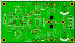
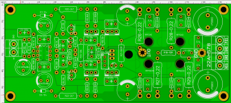
My amplifier boards. Maybe someone will like it....
Attachments

Last edited:
My amplifier boards. Maybe someone will like it....
You need to add sufficient space to attach heatsinks or at least small pieces of aluminium to the driver transistors. On the single pair output board these will get warm and i expect that will also be the case for the dual pair output board.
Otherwise the boards look Ok, despite the components being rather spaciously arranged.
The use of a ground plane is interesting and there are some who would not use that.
- Home
- Amplifiers
- Solid State
- LatFet Amp Based on Philips AH578