The beauty of the lateral mosfet is the bias stability. I did up Bob Cordell's DH-220C design, it is rock steady, no bjt design can do this.
Lateral mosftes have a positive temperature coefficient so increase in resistance as they get hotter which lowers the current.
I have seen zeners across GS to limit max current.
Lateral mosfets tend to protect themselves.
I should have said the bias was stable from power up to op temp with static bias, no signal.
and I am proven wrong by johnego's bjt cfp designs. Good stuff, I never liked the long trace length of the remote mounted sense device in the VAS ckt.
Cheers
and I am proven wrong by johnego's bjt cfp designs. Good stuff, I never liked the long trace length of the remote mounted sense device in the VAS ckt.
Cheers
Last edited:
I also noticed some resistor values have changed from v1.0 to v1.1 of the schematic:
v1.0 - R14 / R18 = 1K2
R45 = 550R
C22 & C23 wrong polarity
v1.1 - R14 / R18 = 680R
R45 = 560R
C22 & C23 correct polarity
v1.0 - R14 / R18 = 1K2
R45 = 550R
C22 & C23 wrong polarity
v1.1 - R14 / R18 = 680R
R45 = 560R
C22 & C23 correct polarity
i always thought for CFP, you want temp tracking device tracking the drivers but not the outputs?
care to share what are you doing differently?
mlloyd1
care to share what are you doing differently?
mlloyd1
The Vbe transistors in my BJT CFP amps have also no contact with drivers/output/heatsink. Rock stable too 🙂
I also noticed some resistor values have changed from v1.0 to v1.1 of the schematic:
v1.0 - R14 / R18 = 1K2
R45 = 550R
C22 & C23 wrong polarity
v1.1 - R14 / R18 = 680R
R45 = 560R
C22 & C23 correct polarity
V1.1 is with correct values. R45 changed to 560R as I could not find 2W 1% metal film resistors of 550R.
Attachments
Last edited:
i always thought for CFP, you want temp tracking device tracking the drivers but not the outputs?
care to share what are you doing differently?
mlloyd1
You are right.
i always thought for CFP, you want temp tracking device tracking the drivers but not the outputs?
That's right 😉
That's right 😉
OK, I know my English is not perfect, but you said "The Vbe transistors in my BJT CFP amps have also no contact with drivers/output/heatsink." and that's not correct.😉
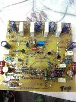
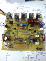
I have instal some parts not exactly the same at the schematic.
I hope that will be ok.
As i haven't any 2K7 2W i have instal 3K9.
Testing this with 50v i see 8mA through the zener.
I have instal 150K//150K for the input 75K resistor.
For vas load 91R resistor i have instal 100R//1K.
All the decoupling caps installed 100uf/63v.
Still some parts are missing.... like the feedback resistor 560 R/3W.
For protection diodes i have UF5404 & 1N 5408,what is preferable,fast or slow recovery?
I hope that i will come close to finish soon
Attachments
Last edited:
I have instal some parts not exactly the same at the schematic.
I hope that will be ok.
As i haven't any 2K7 2W i have instal 3K9.
Testing this with 50v i see 8mA through the zener.
I have instal 150K//150K for the input 75K resistor.
For vas load 91R resistor i have instal 100R//1K.
All the decoupling caps installed 100uf/63v.
Still some parts are missing.... like the feedback resistor 560 R/3W.
For protection diodes i have UF5404 & 1N 5408,what is preferable,fast or slow recovery?
I hope that i will come close to finish soon
When you put DC servo opamp in the socket current through R13, R19 will increase and 3k9 will be to high and nothing left for 15V zener to regulate.
Be aware that D1 and D4 are 12V zeners, and for 1N4148 not so important fast or slow.
Sorry dadod i ask about D5,D6.When you put DC servo opamp in the socket current through R13, R19 will increase and 3k9 will be to high and nothing left for 15V zener to regulate.
Be aware that D1 and D4 are 12V zeners, and for 1N4148 not so important fast or slow.
Sorry dadod i ask about D5,D6.
And I answered both, so not critical replacement for D5, D6, use what you have.
Hi Damir,
I like your topology a lot - providing high open loop speed and linearity, very good harmonics profile. Bravo.
As a suggestion - I would try to replace the global feedback network with 18-20db ODNF - it may result in a super-natural sounding amplifier. Worth live-testing.
Cheers,
Valery
I like your topology a lot - providing high open loop speed and linearity, very good harmonics profile. Bravo.
As a suggestion - I would try to replace the global feedback network with 18-20db ODNF - it may result in a super-natural sounding amplifier. Worth live-testing.
Cheers,
Valery
Hi Damir,
I like your topology a lot - providing high open loop speed and linearity, very good harmonics profile. Bravo.
As a suggestion - I would try to replace the global feedback network with 18-20db ODNF - it may result in a super-natural sounding amplifier. Worth live-testing.
Cheers,
Valery
Thank you Valery. Some years ago I simulated ODNF and have found that is quite sensitive (read not easy) to set it correctly, never tried real amplifier.
What is your experience with ODNF in real amp?
Best wishes,
Damir
OK, I know my English is not perfect, but you said "The Vbe transistors in my BJT CFP amps have also no contact with drivers/output/heatsink." and that's not correct.😉
The Vbe transistor in my BJT CFP amp has no contact with driver transistor or output transistor or any heatsink and the amp is rock stable. That's a situation. Of course, I started like everybody else, i.e. the Vbe transistor monitors the drivers temperature.
The Vbe transistor in my BJT CFP amp has no contact with driver transistor or output transistor or any heatsink and the amp is rock stable. That's a situation. Of course, I started like everybody else, i.e. the Vbe transistor monitors the drivers temperature.
You say that, but without any proof?
Please Damir, because i want to stay on the safe side, i will use one pair of latfets for the first test. Any disadvantage?
What is the bias setting?
What is the minimum voltage power supply (with zener resistors modification)?
Thanks.
What is the bias setting?
What is the minimum voltage power supply (with zener resistors modification)?
Thanks.
Last edited:
Please Damir, because i want to stay on the safe side, i will use one pair of latfets for the first test. Any disadvantage?
What is the bias setting?
What is the minimum voltage power supply (with zener resistors modification)?
Thanks.
That is OK, just don't load it to much. The bias setting between 120 to 130mA per output pair.
It is design to work on +-45V to +-55V without need to decrease zener resistors, and with +-40V if you decrease zener resistors to 2k.
That is OK, just don't load it to much.
It is design to work on +-45V to +-55V without need to decrease zener resistors, and with +-40V if you decrease zener resistors to 2k.
Ok. thanks!
I hope to be tested today! 😉
- Home
- Amplifiers
- Solid State
- Lateral CFA 120W - BSA