Greetings
Hello Xblocker, The Mahaly Traub system along with other early pioneering mechanical tv system inventors showed great skill in their acomplishments. At that time in the early 30's there was no other way than by mechanical means. Trying to align many small mirrors in the correct place is not easy. I have mentioned the patents I have studied to gain an understanding of mirror systems and if you look at the Traub patent you can see the mirrors are very small probably no more than 1/4 inch in width perhaps 1/2 an inch tall. It is possible, if one had the money and if all mirrors were prcision cut they could be butted up to each other around a raised precision circle say 1/4 inch thick, and held in place by a flat rubber belt or suchlike with a very thin pin in between each mirror to stop it shifting and then adjust the rotating mirror speed to spend just enough time on each mirror to form a tv line. You would need 312 mirrors one half circle and 312 mirrors the other half . Some tv lines top and bottom of the picture are not needed for display so the laser beam not hitting some mirrors is no problem. Your other point reduced scan angle is also a problem but notice Traub and others use a final lens to project onto the screen. A projection lens would do the job. I have several here from old film projectors.
The only reason I am using a rotating mirror is to gain an understanding of the means of laser projection.
Some of the things I have learned are ;
A An ordinary polygon with say 8 sides has to rotate very fast.
B Mirrors can be used to reduce the polygon speed
C Mirrors are difficult to align.
D Mirrors reduce light brightness.
E Mounting surfaces have to be exceedingly flat and square to obtain good reflection geometry
I think the most important thing I have learned is with more facets on a polygon, the speed comes right down from very high to ordinary say under 10,000 rpm.
I am trying to project 312 lines (one field) at 50 fields per second. 50 per second times 60= 3000 rpm. I am happy with that sort of speed. The most number of polygon facets I have seen is 50. Thats 1/6th of 312 approximately so I would still have to rotate the polygon at 3000 times 6 = 18000 rpm. Too high for me. Keping to 3000 rpm and using a 50 mirror polygon I could use 6 laser beams all aimed at the polygon and draw the 312 lines in 6 groups.
Laser #1 draws top 50 lines in one revolution
Laser #2 draws the next 50 lines in the same revolution
etc
One revolution of the polygon gives me 312 lines. Revolution speed is still only 3000 rpm
I would need a memory for the tv field and a means to output each of the 6 groups of picture information so that as the polygon went around each laser beam was drawing tv lines. Should be 6 times brighter picture as well. This idea has possibilities because laser diodes are cheap. Polygons are cheap. A memory system must be possible at not too much dollars and the only thing I have to buy is a 50 mirror polygon wheel. If its say 3 inches in diameter should be able to rotate at 3000 rpm safely without disintegrating and the scan angle is 720 divided by 50 = 14.4 degrees which is perfect for my lounge with a projection distance of about 24 feet. That should give me a 6 foot wide picture. ( But I might not see it because of lack of light)
Remember I am still only displaying one field at a time and not interlacing just drawing the fields on top of each other so the picture is not as good as it should be.
Continued next post.
Calculations using 312 tv lines, 50 mirror polygon, 14 degree scan angle
1 laser 18000 rpm
2 laser 9000
3 laser 6000
4 laser 4500
5 laser 3600
6 laser 3000
7 laser 2571
8 laser 2250
9 laser 2000
10 laser 1800
Need a memory system, a means to aim 6 or so lasers at a polygon very closely so there are no gaps between groups of lines, a 50 mirror polygon and a means to introduce slight beam shifts for interlacing. If I had a laser bar with 312 lasers I could sweep that from left to right and generate a tv field easily. I would need a means to modulate each laser but the picture should be quite bright and possible at some time in the future to upgrade to colour. These components are probably not very far away with the speed of technological progress. Pal television, even though it is a 625 line system I understand when displayed on a television set is 768 pixels * 576 pixels. So a 576 laser bar swept horizontally across the screen would give a complete frame including interlace when driven correctly. Anyone know if that is correct .
Xblocker Your experiments are most interesting. Would you be interested in researching how we could use a laser bar if available how much, are they collimated and can each diode be individually modulated.
Fiat1 You have a scheme in mind for beam deflection. Hows it work. Are you happy with it .
Darrell Thanks very much for info.
In the meantime I am looking harder on the net for laser diode modulators. Not many offerings. I have not finished that yet and will report soon.
Hello Richard,
The interlace scanning isn't a hard problem. I haven't tried yet but i think it can be solved by offsetting the y- scanner v-sync of the 2nd frame +/- some mV and then switch back again.
Little bit harder would be the Laserdiode multiplexing because they need more complex drivers than LEDs, which have only one hot driver connector and can be simple modulated. If I would realize your idea with 6 LEDs, theoretically I would do this:
Drive the six LEDS with videosignal one after the other switched on and off by h-sync. A frequency divider (15625 / 6 =2604 Hz) generates a secondary y1 sync.This must be transformed with D/A transformer into a sawtooth-signal looking like a stair. This happens 52 times and 312 lines are written. Then a new frameloop begins.
Whats practically hard to realise is- again - the optical assembly.
1. How to collimate several lasers or LEDs exactly on one small facet of polygon?
2. The jump of y-scanner to the next 6-pack of lines without delay? There is always an inertia of mirror, depending of weight and sizes, so the lines would blur. there would better be a second polygon for y-scan...!?
3. Doing this with lasers there will be huge amount of electronics and cost.
On this second-hand laser webside there are some cheap offers:
- AOM red mod.10 MHZ 49.-DM that's about 22 us$
- polygon scanner 15 facets, 10000 rpm, incl.contr. 45 DM ~ 20 us$
Considering the brightness of these laser images i would not worry about now. We could be happy if we could see an image at all.! As big as a stamp!
What about using a DLP or LCOS poly-si chip, beaming with RGB Laser on it? That would make the colourwheel useless, which absorbs a lot of luminance. The 3 times sequential field changes could be switched by 3 lasers with a 150 Hz frequency, no further laser modulation is required. Only dichroic mirrors for integrating the beams. Also probs of heat, lifetime and costs of actual lightbulbs could be eliminated. May be this is the solution of the future! My hope is to get reasonable RGB laser anytime..
Question to FIAT1: What's your setup? Size of mirrors? What are the frequencies and signalforms to drive your mirrors?
Greetings xblocker
Hi Remp. Yeah my system uses 2 mirrors. The mirror ar relativly small, they sit atop of two springs, one can rock vertically and the other horizontaly. Each mirror is is rocked by an electromagnet operating with an apropriate sweep freqency. I have it set up so a beem of light beems onto one mirror, then onto the other and then onto a screen. I have a raster thing happening, the only problem is that using sine wave scaning produce shading of the image where the edges are brightter then the middle. What kind of frequency does a CRT use to scan?
Greetings
Xblocker, Regarding the multiple lasers, I dont think I explained what I was thinking about very clearly. We know we can aim one laser at a polygon and get a scan line. We also know second hand polygons usually have small number of mirrors so usually the scan angle is quite large 90 degrees or more and we also know trying to get the required high speed scan rate for tv with second hand ex printer polygons is difficult.
One solution is to outlay the money and buy a new polygon from a specialist company which will do the exact job. These are priced starting at over 1000 dollars and upwards . Then there is the cost of the motor controllers . On this shoe string low budget small scale project my wife stole my bank card and won't give it back. So I thought if I could get a polygon mirror assembly with 50 facets the required motor speed will come down to not so fast, and if I could somehow use 6 laser diodes instead of one the polygon speed would be even less. And the picture should be more or less 6 times brighter.
The way I thought it could work is like so. First store one field (312) lines in a memory. Dont know how but it must be possible. Next have the polygon rotate one turn. With one laser that one turn with 50 facets would be able to draw 50 lines. So with 6 lasers in one rotation we could draw 6 groups of 50 lines which makes a total field of 300 lines (nearly 312) In that one turn it will allow the 6 lasers to draw 6 parts of the raster by getting the picture information from the memory. Might need 2 memories, one to write data to the lasers and one to store the next field.
Aligning 6 lasers may be difficult or it may not. Most low power laser diodes are 5.6 mm and there is a little keyway on them which could allow another beam through. Half that is 2.8 mm What if we say the top laser is 24 inches from the polygon, the next one is 25 inches from the polygon and a little bit lower so its beam goes under the first. Now you have to add a small amout for heatsink material say 2 mm so that means the second laser is about 2.8+2mm say 5 mm lower than the first. It should be possible to slightly angle the second laser upwards just a bit so it hits the polygon and is more or less in the right place on the screen. Same with the other lasers or only 2 if 9000 rpm is acceptable. Not a very scientific solution but could work. This is for a 50 facet polygons which are not very common.
Frame scanner I agree we need a frame scanner. I understand frame scan is much less difficult than line scan so have not worried about it. Could be your mirror on a loudspeaker idea or a galvanometer
Possibilities then are
(A) 1 laser, 50 facet polygon at 18000 rpm will give you one Pal tv field. Scan angle 14.4 degrees.
(B)1 laser 8 facet polygon at 3000-6000 rpm with assisting mirrors MAY allow the high scan rate but probably at reduced scan angle so need a projection lens probably.
(C) Multiple lasers could be used, could probably be aimed onto the polygon, could most likely give more light but needs more complex electronics to store fields.
I am still on (B) until I find it is not feasable. Presently, while waiting for modulator parts I am using two 8 facet polygons to see if there is a way to get high speed scanning without high rotational speed.
As mentioned previously with my single 8 facet polygon, I have a ring of raster lines on the wall with sync pulses and modulation from a tv signal generator, and I have had 8 of these lines formed into a small raster which looked terrible. I study these lines every night looking for a breakthrough. It will come, somehow or other we will get a picture. Latest info I have gathered. Pal 625 line system. One tv line is 64 microseconds. Trace time is 52 microseconds. Retrace time is 12 microseconds. Presumably retrace time is front porch+back porch +sync pulse. Front and back porch are blank periods before and after sync pulses. This means retrace time is nearly a 1/4 of trace time.Thanks for DM to US conversion, will look at site some more.
Fiat1 Your idea is very good but you will have problems with horizontal scan rate. For PAL tv 15625 lines per second vertical 25 frames per second. NTSC USA system not the same but pretty close. Its the high horizontal scan rate that is stopping us from buying not too expensive part or making something. On your system you should reduce all H scan parts to the very minimum. You need extremely light weight moving parts and powerful electric coils to get even close to what is needed. It is the simplest way of doing it and I really hope you can get it going but making a scanner like that be prepared for a lot of trial and error. Any help you need glad to do it. If you get it working right I will throw out my polygons anyday and use your system.
greetings everybody,
Hello Richard, now i think i checked what you explained. You want to divide 1 frame into a 6-pack of lines stored in 6 different video ram buffers and then read out to laser simultaneously. All 6 lasers should work at the same time. Right?
good idea, but a complicated task. First there must be a A/D conversion of 1 frame, data must adressed to 6 independant ram buffers. A decision has to be made about the pixelclock, because digital storage needs data for every pixels luminance information. Full PAL resolution needs 768 hor. pixels. That means a pixelclock (bandwide) of 15625 x 768 = 12 MHZ.After storage of 1 frame the read out of these 6 sub frames begins with D/A conversion. The driver architecture of this arrangement is little bit similar to DSTN- LCD panels (dual-scan), where in a 640x480 resolution the 1. and 241. row are written simultan. So here we would start writing row 1, 53, 105,...263 at the same time going up to 52, 104,...312. I'm thinking about, if this means that the read out of ram and facet speed of the polygon can be 1/6 slower as hor.frequency. Maybe it could be done if the pixel read out could be different clock as pixel read in. Actually i don't know.
An advantage of this solution is, there is only 1/6 vertical deflection angle. All that is pretty complicated, because there must be a knowledge of graphical processor programming and SMD handling cababilities. I'm well familiar with computers, but programming todays hardware components is too hard for me. What we need here is graphical interface + complex laser controller in full motion RGB. Realtime! Engineering at it's best..!
xblocker
Xblocker. Your explaination is exactly right, I like your phrase a six pack of lines. I understand your concerns regarding programming todays hardware components. Everything in the electronics world changes so rapidly. Its actually part of the fun dont you think. Things that were impossible a few years ago are now able to be done and I have found many a time that modern IC components are extremely capable and usually inexpensive. Remember the idea of using 6 lasers was just a suggestion, something to think about and it has some considerable advantages such as bringing the polygon speed into a range where cheap second hand polygon motors can be used, keeping a usable scan angle and perhaps the most important, increasing the available light. The downside is figuring how to store the data for the lasers and output it when required. We can do the first 3 and only number 4 is a stumbling block. 3 out of 4 is actually pretty good.
I think we are making great progress with your contributions and fiat1 and many others who have contributed valuable information. Just persuing multiple lasers for a moment did you find anything out about a whole bar of lasers. Say 625 lasers and there is a whole frame. Scan that from left to right 25 times a second which is not all that fast. Picture lines all on screen at the one time should make a much better and brighter picture than starting at the top and drawing a pixel at a time right down to the bottom. And it would be economic because one powerful laser is probably going to be very expensive and use a lot of power. Most bar lasers cannot be accesed individualy for modulation but I understand a German company makes bars that can be. These thoughts are just possibities at the moment. Something to chew over and consider because so far there is no inexpensive laser projector anywhere. There are big systems built by large companies but for the DIY person there is nothing. No kitset of parts, no technical documents describing how to go about making your own. We are the ones who are doing it. I am still working with my 5 milliwatt laser and my ex printer polygons and will continue with that for a time. There are possibilities there. Its just not the easiest thing to see how. Just to spur things on I have set myself a goal. A picture on the wall any size but it must be a reasonable picture before the end of March 2002.
I think we are making great progress with your contributions and fiat1 and many others who have contributed valuable information. Just persuing multiple lasers for a moment did you find anything out about a whole bar of lasers. Say 625 lasers and there is a whole frame. Scan that from left to right 25 times a second which is not all that fast. Picture lines all on screen at the one time should make a much better and brighter picture than starting at the top and drawing a pixel at a time right down to the bottom. And it would be economic because one powerful laser is probably going to be very expensive and use a lot of power. Most bar lasers cannot be accesed individualy for modulation but I understand a German company makes bars that can be. These thoughts are just possibities at the moment. Something to chew over and consider because so far there is no inexpensive laser projector anywhere. There are big systems built by large companies but for the DIY person there is nothing. No kitset of parts, no technical documents describing how to go about making your own. We are the ones who are doing it. I am still working with my 5 milliwatt laser and my ex printer polygons and will continue with that for a time. There are possibilities there. Its just not the easiest thing to see how. Just to spur things on I have set myself a goal. A picture on the wall any size but it must be a reasonable picture before the end of March 2002.
Hello
WHat I would like to know is, what kind of frequency is used to drive the coils of a CRT TV? What are the exact frequency's for horizontal and vertical scanning? Has anyone of you guys thought of building a syustem like this- http://pyanczer.home.mindspring.com/Tour/scophony.html
WHat I would like to know is, what kind of frequency is used to drive the coils of a CRT TV? What are the exact frequency's for horizontal and vertical scanning? Has anyone of you guys thought of building a syustem like this- http://pyanczer.home.mindspring.com/Tour/scophony.html
Greetings.
Fiat1, Thanks for the web site. Did you see the high motor speed of 39,600 RPM for old 441 line tv and it needs higher motor speed for modern tv systems. The high speed is one of the reasons you don't see laser projectors in the shops.
Inside a crt
For European PAL tv Horizontal frequency 15625, Vertical frequency 50
For American NTSC tv Horizontal frequency 15750, Vertical frequency 60
Hello everyboy,
Richard, i think the main reason, why you don't see laser projectors in the shops isn't the highspeed motor problem, it's the lack of small, low power RGB systems with laser diodes. All systems i know use huge laser systems, which are separate and connected via fiber mono mode LWs to the projection head with its scanning systems. Not all commercial scanning systems use polygons. Some of them use monochromatic reflective LCDs. In that case there's no need of modulating the lasers itself, because this is done by the LCDs.
Another case are these micromechanical scanners which are 'real' scanners. If you wanna know more about these go to google and search for 'laser scanner mems display'. There is a lot of stuff out there over the web.
I think if we would use an highspeed polygonscanner we cannot take the polygon from here and the motor from there. If the speed is to high, there might be an 'out of balance' and everything will blow up.
Ok, if we are brainstorming, we could consider other possibilities. What about modification of the Nipkow disk. If we use a normal CD with tiny wholes 5 mm from the outer border and with a distance of 10 mm from each other then we get about 25 wholes in a circle. Then we must speed up the disk to 625/sec (37500 rpm) to get hor.frequency. The result should go onto y-scanner and then to projection lens. Before, the laserbeam has to be widened to a line with 10mm with cylindric lens, so that 1 whole of the disc is moving along that line. The destination of the small wholes could be managed by a layout progam and printed out onto CD label.
I know this is not as easy as it sounds, but it was also a consideration i did a couple of years ago.
Actually i would like best to canibalize a DLP projector to get the micromirrors.
Fiat1, i suppose you can't move your mirrors at horizontal Frequency because of the inertia. Thats the main barriere we talk about all this. Further, the mirrors don't only have to be tilt, they must be tilt like a sawtooth, first linear and at the end like a shot back into startposition.It's physically nearly impossible.
Happy engineering and happy new year to all !
xblocker
Greetings
Xblocker, I think if you can't scan at the right speed your wasting your time because the rest won't work. You think its a lack of suitable light. More than likely unless you have a huge amount of spare cash then there are no problems so we are both right.
I had a look at "laser scanner MEMS display". These systems based on micromechanical components have been on the web for years. They all keep saying next year or under development. Everyone is trying to make another large screen projector because it's a projected 20 billion dollar market over the next 5 years. The only company offering micromirror projection in the shops after 20 years effort is Texas Instruments using their DLP system. There are several others but you try and buy their components. No DLP chip or other types of deflection chips are available to the DIY person via regular parts suppliers because it means if I buy a chip and you buy a chip and other DIY people buy chips and get it going thats fewer complete systems that will be sold by the projector retailers. Some years ago Texas Instruments offered demonstration kits for their DLP system at about 6000-7000 dollars but I have not seen these kits available anymore. You have to go and buy a complete projector. Buy it, use it then sell it or throw it away. Thats the way it is now. No room for DIY people because these things are getting so technically complex and sellers want to sell complete systems not parts to make one.
Have a look at the lcd projector thread. They have been going a lot longer than laser projector thread and they have a number of problems even using available lcd panels. I think the main reason is many DIY people are not familiar with optical systems. Thats why I am going real slow on this and explaining everything as clearly as I can so other DIY can see what I am trying to do and how.
There are no laser projectors in the shops , we have to build something ourselves. It cannot be too expensive or you might as well buy an LCD or DLP projector. It cannot use parts that are hard to get and it has to be relatively simple, or if not simple at least understandable and can be built.
I am sticking with polygons for this small scale laser projector test. The present bits I am working on are Can two polygons work together to lower the speed requirements, and a modulator for the laser. Will report progress soon.
Best wishes for the new year.
Hi Richard,
you're completely right, on one hand we have a mass-market, but for DIY there is only small offer. But we must be aware that we are looking for hitec- components, which are rather specialized. Some weeks ago i searched for a single TFT-controller modul with VGA or VIdeo input. If you wanna purchase this as single component you are lost. The price is often higher than a complete TFT monitor, espacially here in germany. I have a projection panel for overhead, where the controller have died. First i searched circuit schematics - no go! Then i tried to get any controller. Heavily overpriced! If i want a PCI card for DVI it would be easy and cheap, but over the years there was chaotic interface standard so it might not work. The heck with it!
I have little idea of this 6 laser array. Why not simply connect 6 fiber optics pipelines? They are thin enough to arrange them inline side by side. I'm not quite full up to date about fiberoptics but as far as i know a monomode fiber would fit the best.
Concerning 2 polygons, it's very tricky. At the first sight i would say, the deflected line from the first mirror must not be longer than one facet of the second polygon but maybe i'm wrong here. We should have simulation software to prove this. But we will have a expotentiated synchronisation problem.
With 1 polygon we can also double the deflection angle, if we reflect the laser twice. First into polygon facet, then into stationary mirror, from there back on facet again and finally to the screen.
Now it's time for little brain-jogging!
Greetings
xblocker
Greetings
You remember the calculations I did several posts ago on the speed for a 50 facet polygon which showed for a 312 line field I need 18000 rpm. Just to see how much one of these factory built polygons would cost I sent off several enquiries to polygon manufacturers. Here is the first reply.
Hello Richard, Thank you for your inquiry.Based on medium specifications. Budgetary estimate for quantity one is $5000.00 This would include drive control card. I have attached a sheet for you to complete so I have some idea of what exactly is needed. Looking forward to hearing from you soon.
That company gave me a reply in one day which I thought was very good.
As you can see the price indication is 5000 dollars. Thats U.S. dollars so my buying price here in New Zealand would be approximately 14 thousand dollars. I imagine prices from other manufacturers would be similar. Even at a tenth of that price it would still be outside my price range because this is a small scale test.
Here is a simple experiment to show you can get much more speed out of a simple low cost polygon.
Turn down your laser beam power if you can.
Do not look into or at a laser beam, use a piece of paper to locate a beam
Do not put fingers on the polygon facets because your skin has oil
Look at the beam spot on the facet at an angle so you dont get the laser beam in your eyes.
Here is the experiment
(A) Aim a laser at a polygon facet
(B) Place an upright mirror to intercept the reflected beam
(C) Get the reflection from the mirror to hit the same polygon facet.
Slowly rotate the polygon by hand so the laser beam moves along the facet.
Look at the facet at an angle so you dont get the laser beam in your eyes
You will see a slowly moving spot on the facet and, at some point, another spot moving at very high speed.
The slowly moving spot is the unaided speed
The fast moving spot is 10 or 20 times faster and is the one I am using.
If you do this experiment you will see the high speed spot is obtained by the polygon and a mirror acting together.
I need 312 lines (one PAL tv field) per revolution of the polygon.
I have 8 facets on my polygon
Unassisted will only give me 8 lines per revolution.
I need speed assistance from some mirrors
How many mirrors
312 divided by 8 is 39.
I need 39 mirrors.
An 8 facet polygon gives 720 divided by 8 is 90 degree scan angle.
I need to fit 39 mirrors perfectly in a 90 degree quadrant at a radius from the motor shaft.
I do not know what is the correct radius for the mirrors but if they are all the same width and they fit perfectly in a 1/4 of a circle it should not make any difference. The mirrors look like they should be 1/2 inch wide. To be confirmed
Motor speed calculations one field of 312 lines in 1/50th of a second is 50 fields per second is 3000 rpm
Setup with just one mirror
Start with no motor speed
Most ex printer polygons have a small facet thickness usually 4-6 millimeters.
Thats not much room for a double reflection so you have to be accurate in laser beam and mirror placement
Put your laser 30 inches from the polygon. Aim it at the motor shaft
Your laser needs to be exactly horizontal and then the beam tilted up a very small amount Approximately 1/4 of a degree
Your polygon should be positioned so the laser spot is towards the bottom of the facet that is facing the laser.
The polygon facets should be horizontal
Place a 2 inch wide mirror 15 inches from the polygon
The reflection from the mirror should hit the polygon towards the top of the facet.
Run your polygon at 3000 rpm
The reflected scan will just go over the top of your laser diode with nothing to spare.
The scan angle is about 15 degrees
Place a white paper behind the laser
If you have an 8 facet polygon you will have 8 tv lines on top of each other. A frame scanner would prove the point.
8 tv lines with 1 mirror equeals 312 lines with 39 mirrors
I am still working on my modulator.
Xblocker; Thanks for your comments and suggestion re fibre optics. You are not really serious about a Nipkow disk are you. 37000 rpm at cd disk diameter is close to the speed of sound. I dont think CD's were made to revolve that fast. Just pulling our legs right ??
Hope everyone had a good Christmas
Greetings
Forgot to mention I have made enquiries for HOE items. An HOE is a Holographic Optical Element that can, amongst other things, replace a polygon. Have only tried one company who advised they were bought out by another company and were now a research and developement division and could not help.
Forgot to mention I have made enquiries for HOE items. An HOE is a Holographic Optical Element that can, amongst other things, replace a polygon. Have only tried one company who advised they were bought out by another company and were now a research and developement division and could not help.
Hello,
Richard, your math calculations about number of mirrors seem to be correct. To calculate radius of 90 degree mirror segments (aproximated):
mirrorsegment = 2*radius /4*39 = radius/78.
Radius = 78*Mirrorsegment.
Well, it isn't 100% correct, because it's the length of the part of cicle segment, but may be a start.
Greetings
xblocker
Greetings
Thanks very much for info Xblocker. Please accept my apology for commenting on your nipkow disk idea. That was bad manners on my part and I am sorry.
Placement of mirrors is a problem with no simple solution. I have positioned mirrors many times without much success. Each mirror has to be exactly vertical, each mirror has to be exactly on the radius and each mirror has to be square on to the polygon motor shaft. I have an idea in mind to simplify mirror alignment but before that I have to see if there are 8 raster lines on top of each other as mentioned in previous post.
Greetings
There are 8 scan lines per mirror per revolution.
Simply rotating the polygon by hand shows each time a facet on the polygon is in line with the one test mirror it produces a scan line.. 8 facets = 8 scan lines per mirror. 39 mirrors times 8 = 312 scan lines per revolution.
There are 8 scan lines per mirror per revolution.
Simply rotating the polygon by hand shows each time a facet on the polygon is in line with the one test mirror it produces a scan line.. 8 facets = 8 scan lines per mirror. 39 mirrors times 8 = 312 scan lines per revolution.
Greetings
Using one test mirror I should have, with an 8 facet polygon, 8 raster lines. I did a simple frame scan by wriggling a flat mirror in the scan path. There were 8 raster lines. Large wriggling of the mirror spread these lines a lot but since 8 lines is a small percentage of 312 lines I tried to keep them bunched into about an inch vertically. Looked just like tv lines. Light level dropped but can see them in a darkened room with some ambient. With modulation applied you would be struggling to see a full greyscale picture. As said before, this is a small scale test. With a 5 mw laser I never expected anything better than a faint picture.
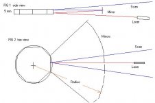
Placing the 39 mirrors is difficult. The mirrors are arranged in a radius around the motor shaft. Unfortunately the laser beam has to pass under the middle mirror and the outgoing scan passes over the top of 5 middle mirrors. This means the middle mirrors have to be short and will be hard to position.
This problem is causd by the thinness of the polygon facets about 5mm. If it was 1/2 inch thick there would be plenty of room. I have drawn the setup and tried to post it. Hope it gets there.
A possible way to overcome this is to aim the laser off centre and shift all mirrors around so the laser beam can see the polygon unobstructed. Could cause some optic geometry distortion.
Using one test mirror I should have, with an 8 facet polygon, 8 raster lines. I did a simple frame scan by wriggling a flat mirror in the scan path. There were 8 raster lines. Large wriggling of the mirror spread these lines a lot but since 8 lines is a small percentage of 312 lines I tried to keep them bunched into about an inch vertically. Looked just like tv lines. Light level dropped but can see them in a darkened room with some ambient. With modulation applied you would be struggling to see a full greyscale picture. As said before, this is a small scale test. With a 5 mw laser I never expected anything better than a faint picture.
Placing the 39 mirrors is difficult. The mirrors are arranged in a radius around the motor shaft. Unfortunately the laser beam has to pass under the middle mirror and the outgoing scan passes over the top of 5 middle mirrors. This means the middle mirrors have to be short and will be hard to position.
This problem is causd by the thinness of the polygon facets about 5mm. If it was 1/2 inch thick there would be plenty of room. I have drawn the setup and tried to post it. Hope it gets there.
A possible way to overcome this is to aim the laser off centre and shift all mirrors around so the laser beam can see the polygon unobstructed. Could cause some optic geometry distortion.
Attachments
Hello Richard.
now you're nearly at the same point, where i gave up some years ago. I was unable to place the mirrors in a proper way around the poygon, so that the reflected beams are laying each over the other after passing all mirrors. To make the whole thing flexible i tried to stick them on small magnets, arranging them on a part of a metal ring, but this was not very successful. This metalborder should have had a tap through whole with 2 little screws on top and bottom to adjust each mirror separately and accurately, but this wasn't possible with own work. I know it should be a simple task but in detail it's pretty heavy.
I never had an optical bank with suitable components, so i did the last step before the last but one.
I tried the syncronisation-control between horizontal sync and polygon motor. I measured the last outgoing mirrorbeam with a photosensor and let the motor speed up until the 15,625 khz frequency was reached .Then a trigger switched off and on again automaticly, until there was a balance on the required frequency. It depends off the type of motor you are using. If it accepts any sort of sync signals the better. But of course it will not accept h-sync speed, so h-sync must be divided into motor-compatible sync-ratio.
But thats a real problem because of the mass of polygon and rotating motor components.They must react quickly on the slightest shifts of sync, or you will see garbage image. What kind of control ability does your motor have?
In general i would say, i would have been happy if there had been forum like this to discuss such questions. Five or six years ago, there was nobody, who wanted to discuss about DIY-laser projectors, so i'm happy that there are guys out there, who are interested in such a project.
Keep on track!
Greetings
xblocker
Greetings
Hi Xblocker, thanks for info. Most of the mirrors are not in the way of the laser beam or the outgoing scan. Only the middle 3 or 4. Maybe glue a stick on mirrors and pass stick through a ring like a curtain hook with small rubber grommet. Screw hook into place, slide the stick through and three kinds of movement. up/down left/right and forward/back. Side to side movement of ring maybe could use a thin flat wood strip pivoted say half an inch behind the mirror. Screw curtain ring into flat strip. Move flat strip left or right. Putting a lever on the mirrors might make it easier to position them. Remember, the trace time is only a bit more than 4 times the retrace time so a gap between mirrors is ok.
But I am not getting into that until 100 percent sure the fast scan mentioned in previous posts is fast enough and suitable for the job. The only real way to tell is
(A) modulate the beam
(B) set up one or two mirrors
(C) install a frame scanner
Your comments re motor speed is good. I think you can rely on the H sync from the tv transmitter as being very stable. The motors I have are controlled by an external clock square wave. If I give it 3000 Hz it runs at 3000 RPM. So far the motors show very good stability probably due to the rotating mass. There is some motor speed drift but my square wave generator is only average. In the printer they were used in there was an end of scan fibre optic detector that either altered the motor speed or altered the pixel clock to write the dots on the page. I think the motor will be alright over one field and there is quite a long frame interval to adjust motor speed by a comparator. I could use H sync divided by a factor to get the square wave to run the motor with a position detector for correct phasing. Or a crystal controlled driver. If the speed does vary and is brought back to correct speed there will be a shift in the picture where things dont line up vertically. Have to wait and see how serious the problem is.
Here is the problems with modulator. So far after much web browsing have not found a totally suitable modulator. John Yurek has what looks like a good one at
www.k3pgp.org
Many specialised modulators available but either digital or expensive or not suitable for my use. Making my own.
There are two points in a laser diode. One point is when the laser is just lasing. That is the dark bit. The other point is just before the laser blows up. That is the bright bit.
It is necessary to work between these two points. Turning the laser right off slows it down. Turning the laser on too much will destroy it. The small mirror in the laser melts or disintergrates then the laser is useless. To make the modulator safe you have to have a foolproof method of limiting laser current to a safe value. I have several lasers. some draw 90 milliamps full power. They are older types. Some draw 35 milliamps. These are more modern types.
All rated at 5 milliwatts power. As always be careful with lasers. Even if they do not look bright they can still damage your eyes.
670 nano meter 90 milliamps dull red not very bright
650 namo meter 35 milliamps lovely deep red good brightness
635 nano meter 36 milliamps red with slight tint of yellow extra bright.
I use 10v regulated supply with 330 ohm 20 watt resistor. Maximum current that can flow is 30 milliamps. Setup is 10v >resistor> laser diode >transistor> ground. There is a 50k potentiometer from 10v to ground which feeds the transistor base via 50k resistor. This sets the laser to half power. Modulation applied via 100k capacitor and 10k resistor to base. There is a shottky diode across the transistor to limit any possible reverse voltage to 0.3 volts.
This seems a safe setup and it does vork but not very well.
Two problems. The transistor is not fast enough. The modulation drive is not satisfactory. I need to make a pre window for peak white and blanking to just go through. Anything outside these limits will be clipped. So peak white should correspond to maximum laser power and black will be the laser just about invisible. I also need to restore the DC content of the video signal. Another approach is a current stealing modulator where the laser is always at full power except a transistor or FET across the laser turns on and bypasses laser diode current. White is no current bypass. Black is current bypass on. Different shades are how much bypass is on. You still cannot let the laser turn off completely or it cannot be modulated quickly.
As mentioned I have a single sided mirror that is attached to the top of the polygon motor. With this I can see individual tv lines spread in a ring around the room. Last night I hooked up my television set video out to the modulator. I sat and watched tv for the first time on my home made laser projector. Very satisfying feeling. Even though the picture was horrible it was still very satisfying.
- Status
- Not open for further replies.
- Home
- General Interest
- Everything Else
- The Moving Image
- DIY Projectors
- Laser projector