Hello,
Richard, gratulations to your first video sightseeing! getting the laser modulation to work would be fine. I also found this:
http://www.rfe-online.de/_archiv/05/tipps/22.htm
sorry, but I didn't understand your explanation concerning this multi-mirror bank. If only 3 or 4 mirrors are hit by the laserbeam, does it mean that deflection angle is to small ? How is the wide of a single mirror? Remember, if a single mirror is 1 inch you will have radius of 78 inch(approx.) for the mirror array.
Considering motor sync: It's good that you have digitally controlled rotation speed. That means we can make a simple digital division. Digital divider can be set up to 256,32,16,8 = 312 to get a result of 50 Hz = 3000 RPM. But thats nearly the same as we would only take v-sync of video as sync reference. This isn't real h-sync control because of the high division ratio of 1 : 312 ! There will be a micro-shifting within the frames and the lines won't start at the same point. Motor can overshoot at the beginning of a frame and undershoot(?) before frame ends. That's in my opinion the main problem of all. The question is how quick will the motor react after he gets the sync -impulse, and how quick it will slow down again. We're talking about micro seconds here !
What i said in a previous post, professionel manufacturers don't adjust the motor to the sync, they adjust the sync to the motor via ram buffers. Because electrical data can be processed faster than mechanical changes can be done due to the mass. We can only hope if we see something at all, that looks like a video image.
To extract h- and v- syncs from composite video have a look on:
http://home.t-online.de/home/j.redelfs/sync.htm
Beam it !
xblocker
P.S. Seems we are the only ones to be left here.
Greetings
Hi Xblocker. Thanks very much for info and web sites.
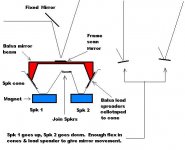
The situation with the mirrors is that all are needed but the middle 3 or 4 have the outgoing scan going right over the top of them with very little space to spare which means they cannot be very high, and the central mirror has the laser beam going underneath it as well. Have a look at the diagram I posted. Here you can see the laser beam underneath, and the scan over the top. This means a few mirrors in the middle have to be short about 5-6 mm high otherwise they block the outgoing scan. There could be a better way of arranging the mirrors but I'm not sure how. The calculated scan angle is 11.25 degrees.
Radius for 39 1 inch wide mirrors in 90 degree quadrant
Approximate only. Mirrors are straight. Circle is round.
39 mirrors in 90 degree is 156 in full circle.
Circumference=2*Pi *R where Pi =3.14 approximately
Radius = circumference / 2 pi = 156/6.28 = 24.8 inches approximately.
I checked this out by drawing a 25 inch radius circle, marked off 90 degrees and can fit 39 one inch mirrors ok.
I can understand your concerns regarding the motor speed. They use these polygons for printers in big quantities where the human eye can spot an error very quickly . My motor seems stable. If the motor is unusable for television I will find another way to scan.
If you look at visits to the site there has been over a 100 in the last 3 days. I would say there is a lot of interest and visitors are checking on progress. Thats not unusual. There are better materials to work with these days which is helpful but other things are happening which I mentioned before. This is a high technology area of work. It can quickly get very expensive and is moving away from DIY persons to big business. Looking down the track one could say whats the point. Who wants a red television. You need much more light to make a usable device. You need colour. TV standards are changing, What are you going to do when HDTV arrives.
You have to start somewhere. A small scale test costs little and shows up quite a lot.
I am making good progress on the modulator.
Hi Xblocker. Thanks very much for info and web sites.
The situation with the mirrors is that all are needed but the middle 3 or 4 have the outgoing scan going right over the top of them with very little space to spare which means they cannot be very high, and the central mirror has the laser beam going underneath it as well. Have a look at the diagram I posted. Here you can see the laser beam underneath, and the scan over the top. This means a few mirrors in the middle have to be short about 5-6 mm high otherwise they block the outgoing scan. There could be a better way of arranging the mirrors but I'm not sure how. The calculated scan angle is 11.25 degrees.
Radius for 39 1 inch wide mirrors in 90 degree quadrant
Approximate only. Mirrors are straight. Circle is round.
39 mirrors in 90 degree is 156 in full circle.
Circumference=2*Pi *R where Pi =3.14 approximately
Radius = circumference / 2 pi = 156/6.28 = 24.8 inches approximately.
I checked this out by drawing a 25 inch radius circle, marked off 90 degrees and can fit 39 one inch mirrors ok.
I can understand your concerns regarding the motor speed. They use these polygons for printers in big quantities where the human eye can spot an error very quickly . My motor seems stable. If the motor is unusable for television I will find another way to scan.
If you look at visits to the site there has been over a 100 in the last 3 days. I would say there is a lot of interest and visitors are checking on progress. Thats not unusual. There are better materials to work with these days which is helpful but other things are happening which I mentioned before. This is a high technology area of work. It can quickly get very expensive and is moving away from DIY persons to big business. Looking down the track one could say whats the point. Who wants a red television. You need much more light to make a usable device. You need colour. TV standards are changing, What are you going to do when HDTV arrives.
You have to start somewhere. A small scale test costs little and shows up quite a lot.
I am making good progress on the modulator.
Greetings
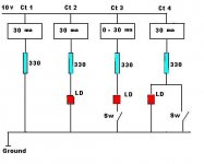
Work on the modulator is proceeding. Attached diagram shows four Circuits
Circuit 1 is a simple resistor and milli amp meter. It shows 30 milliamps. With the power supply steady at 10 volts, 30 milliamps flows. No more can flow. This is the first step towards protecting the laser diode LD from burning out.
Circuit 2 shows the Laser Diode. Once again 30 milliamps is the maximum current so the laser diode is safe.
Circuit 3 shows the laser diode being turned on and off by a switch. There are only two possibilities. Zero or 30 Milliamps. If you replace the switch with a transistor and vary how hard the transistor is turned on, an amount of current between zero and 30 milliamps can flow. This can act as a modulator. The laser diode is protected because maximum current is limited to 30 milliamps by the resistor.
Circuit 4 Shows a switch across the laser diode. If the switch is off 30 milliamps flows through the laser which shows full brightness. If the switch is turned on, no current flows through the laser so it is off. The switch can be replaced by a transistor to vary how much current is bypassed away from the laser. This can give modulation. Once again, the laser can only have 30 milliamps.
Continued
Attachments
Greetings
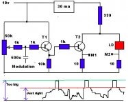
Attached circuit is a developement of circuit 4 in above drawing.
Transistor T1 is an emitter follower to keep loading off the TV signal generator. It also sets the modulation depth by the 50k Pot.
Transistor T2 removes power from the laser. It acts like a variable resistor. When T2 is off it is a high impedance and has no effect on the laser which operates at full power. When T2 is turned fully on, it becomes a low impedance and bypasses all or most of the current away from the laser. The laser is then dark. Driving the transistor T2 in between on and off modulates the laser.
I start like this.
50k pot turned right down
Soft start 10v supply.
Adjust 10v supply until 30 ma flowing through laser diode
Connect scope to monitor point M1
Turn up 50k pot small amount.
Keep turning until modulation shows at M1
Change scope to M2
Observe current in laser diode.
With this circuit, peak white is full laser power.
Modulation reduces laser power until no laser power which will then be black.
Too little modulation laser not at black
Too much modulation laser cuts off and takes time to restart. Slows down modulation.
Having the laser full power equeals peak white is very handy. The laser can not get any brighter and this point then must be peak white. Or using a red laser peak red.
The only other point to fix is black. As mentioned, the laser current can be reduced to zero but this is not good. The laser power needs to be reduced until it is just still lasing. It will be invisible so it is the black we require.
That point has to be fixed solidly.
I have not yet done that yet.
With peak white fixed by maximum laser power, and black accurately fixed by some means, the laser can swing between peak white and black. This is what is required.
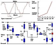
The waveform shows the sync pulses force the laser to turn off. We do not want this. The correct waveform should be the part labelled just right.
I still have work to do to fix the black point.
Then I have to restore the DC content.
Might have to replace T1 with an operational amplifier.
When turning off the power I do this
Turn 50k pot right down
Reduce 10v supply to 3 volts
Disconnect one lead from laser
Turn off main power to work bench.
The reason for this process is I am doing a lot of adjustment to the laser circuit and this way seems the least problems of blowing the laser.
Attached circuit is a developement of circuit 4 in above drawing.
Transistor T1 is an emitter follower to keep loading off the TV signal generator. It also sets the modulation depth by the 50k Pot.
Transistor T2 removes power from the laser. It acts like a variable resistor. When T2 is off it is a high impedance and has no effect on the laser which operates at full power. When T2 is turned fully on, it becomes a low impedance and bypasses all or most of the current away from the laser. The laser is then dark. Driving the transistor T2 in between on and off modulates the laser.
I start like this.
50k pot turned right down
Soft start 10v supply.
Adjust 10v supply until 30 ma flowing through laser diode
Connect scope to monitor point M1
Turn up 50k pot small amount.
Keep turning until modulation shows at M1
Change scope to M2
Observe current in laser diode.
With this circuit, peak white is full laser power.
Modulation reduces laser power until no laser power which will then be black.
Too little modulation laser not at black
Too much modulation laser cuts off and takes time to restart. Slows down modulation.
Having the laser full power equeals peak white is very handy. The laser can not get any brighter and this point then must be peak white. Or using a red laser peak red.
The only other point to fix is black. As mentioned, the laser current can be reduced to zero but this is not good. The laser power needs to be reduced until it is just still lasing. It will be invisible so it is the black we require.
That point has to be fixed solidly.
I have not yet done that yet.
With peak white fixed by maximum laser power, and black accurately fixed by some means, the laser can swing between peak white and black. This is what is required.
The waveform shows the sync pulses force the laser to turn off. We do not want this. The correct waveform should be the part labelled just right.
I still have work to do to fix the black point.
Then I have to restore the DC content.
Might have to replace T1 with an operational amplifier.
When turning off the power I do this
Turn 50k pot right down
Reduce 10v supply to 3 volts
Disconnect one lead from laser
Turn off main power to work bench.
The reason for this process is I am doing a lot of adjustment to the laser circuit and this way seems the least problems of blowing the laser.
Attachments
Greetings
The modulator circuit in the previous post is running quite well. I can see all the cross hatch and checker board patterns from the tv pattern generator.
This is rather surprising because the transistors are audio transistors not video ones. 2n2102 I am looking around for some video transistors and still thinking about how to trim the sync pulses off. Probably just run the waveform through a stage with low HT and cut them off.
The 10 ohm monitor resistors are very useful to see the laser current on the scope. The waveform in the drawing is upside down but thats how it comes out of my 20 year old tv pattern generator. Video out of my nearly new TV sync pulses are down.
Over the next few days I am going to make some squarewave generators. 1 2 3 4 5 Mhz. These are for testing the modulator.
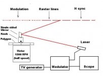
The drawing shows my test setup.
The modulator circuit in the previous post is running quite well. I can see all the cross hatch and checker board patterns from the tv pattern generator.
This is rather surprising because the transistors are audio transistors not video ones. 2n2102 I am looking around for some video transistors and still thinking about how to trim the sync pulses off. Probably just run the waveform through a stage with low HT and cut them off.
The 10 ohm monitor resistors are very useful to see the laser current on the scope. The waveform in the drawing is upside down but thats how it comes out of my 20 year old tv pattern generator. Video out of my nearly new TV sync pulses are down.
Over the next few days I am going to make some squarewave generators. 1 2 3 4 5 Mhz. These are for testing the modulator.
The drawing shows my test setup.
Attachments
Greetings
While working on the modulator I found two points which may be of interest
My original laser diode was a 5 milli watt bare diode with a wavelenght of 670 nm. It was not very bright and needed 80-90 milli amps to run. I decided to buy a newer laser still at 5 milli watts power but a brighter one so I could work without the room having to be in almost total darkness. Purchased a 5 milli watt 650 nm laser MODULE. These are quite cheap and appear to be built in thousands ex Taiwan. 650 nm is supposed to be roughly 3-4 times brighter than 670 for the same power. The module had a small printed circuit board which is there to protect the laser diode from over current. Connecting the red and black leads of the module to my variable power supply via my usual 330 ohm resistor I turned it on at 5 volts. No output. Increasing slowly at 8 volts laser action started and at 9 volts was bright. Much brighter than my previous laser. Current draw was 26 ma. Increasing voltage to 10 volts, current increased to 30 ma. Slight increase in voltage to 11 volts, laser current to 32 ma and then laser current dropped back to 28 ma. Presumably the protection system operated at 32 ma. I reduced voltage to 8v, brought it up again to 10v and left the laser operating at 30 ma for several hours. It did not get hot and stayed very bright. Ddefinitely much brighter than my old one.
Conclusion. 32 ma is maximum current before protection system operates.
Laser will run at 30 ma no worries.
Connecting the laser module into the modulator produced poor results. It would modulate at slow rates up to 20 khz ok but not at video rates. The protection system had to be bypassed. Measuring the red lead I found it was connected to the middle laser lead which is the brass body. Nothing could be done with the red lead. Measuring from the middle pin with a digital (not analogue) meter on diode setting in the ohms range to one pin no connection. That pin must be the photodiode. Measureing from the middle pin to the other pin showed 1789 ohms one direction and open the other. That pin was the other end of the laser diode. Soldered the black lead to it and powered up slowly. Stopped at 10 volt. Laser drawing 30 ma and could be modulated very satisfactorily.
30 ma was for my laser diode. It may be different for yours but the principle is the same.
--------------------------------------
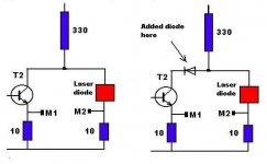
Looking at the modulator circuit in the previous post see how the power supply current can follow two paths. One way is through the laser diode to ground. The other way is through the modulation transistor T2 to ground. I thought this was perfectly safe but noticed sometimes when making adjustments the laser diode would glow fairly bright just for an instant. It was getting extra current from somewhere. I decided transistor T2 might be passing current through the laser when it was only supposed to be diverting current away from the laser. I put a high speed low voltage drop shottky diode in the collector lead of the transistor. Now the transistor could definitely only act as a current divertor. The diode blocks any current that may try to add to the laser current. It works fine. No strange changes to laser light at all.
Laser diodes only need a very small overcurrent and it's good night laser. The diode seems to work fine and has no effect on modulation speed. The drawing shows the added diode. I might put a diode into the laser side as well so both sides would be symetrical. Have not yet.
While working on the modulator I found two points which may be of interest
My original laser diode was a 5 milli watt bare diode with a wavelenght of 670 nm. It was not very bright and needed 80-90 milli amps to run. I decided to buy a newer laser still at 5 milli watts power but a brighter one so I could work without the room having to be in almost total darkness. Purchased a 5 milli watt 650 nm laser MODULE. These are quite cheap and appear to be built in thousands ex Taiwan. 650 nm is supposed to be roughly 3-4 times brighter than 670 for the same power. The module had a small printed circuit board which is there to protect the laser diode from over current. Connecting the red and black leads of the module to my variable power supply via my usual 330 ohm resistor I turned it on at 5 volts. No output. Increasing slowly at 8 volts laser action started and at 9 volts was bright. Much brighter than my previous laser. Current draw was 26 ma. Increasing voltage to 10 volts, current increased to 30 ma. Slight increase in voltage to 11 volts, laser current to 32 ma and then laser current dropped back to 28 ma. Presumably the protection system operated at 32 ma. I reduced voltage to 8v, brought it up again to 10v and left the laser operating at 30 ma for several hours. It did not get hot and stayed very bright. Ddefinitely much brighter than my old one.
Conclusion. 32 ma is maximum current before protection system operates.
Laser will run at 30 ma no worries.
Connecting the laser module into the modulator produced poor results. It would modulate at slow rates up to 20 khz ok but not at video rates. The protection system had to be bypassed. Measuring the red lead I found it was connected to the middle laser lead which is the brass body. Nothing could be done with the red lead. Measuring from the middle pin with a digital (not analogue) meter on diode setting in the ohms range to one pin no connection. That pin must be the photodiode. Measureing from the middle pin to the other pin showed 1789 ohms one direction and open the other. That pin was the other end of the laser diode. Soldered the black lead to it and powered up slowly. Stopped at 10 volt. Laser drawing 30 ma and could be modulated very satisfactorily.
30 ma was for my laser diode. It may be different for yours but the principle is the same.
--------------------------------------
Looking at the modulator circuit in the previous post see how the power supply current can follow two paths. One way is through the laser diode to ground. The other way is through the modulation transistor T2 to ground. I thought this was perfectly safe but noticed sometimes when making adjustments the laser diode would glow fairly bright just for an instant. It was getting extra current from somewhere. I decided transistor T2 might be passing current through the laser when it was only supposed to be diverting current away from the laser. I put a high speed low voltage drop shottky diode in the collector lead of the transistor. Now the transistor could definitely only act as a current divertor. The diode blocks any current that may try to add to the laser current. It works fine. No strange changes to laser light at all.
Laser diodes only need a very small overcurrent and it's good night laser. The diode seems to work fine and has no effect on modulation speed. The drawing shows the added diode. I might put a diode into the laser side as well so both sides would be symetrical. Have not yet.
Attachments
Greetings
The laser modulator is coming along.
Attached diagram shows the setup. This is different from the previous circuit. I use this one with the TV video out and the other one with the pattern generator. R1 strips the sync pulses from the video. R2 sets the black level just at the point lasing starts and R3 sets the gain so the laser is fully modulated. I have no plans for gamma correction.
Works ok. Still using audio transistors 2N2102. . If I adjust R1 to show a little bit of sync pulses scope shows nice square edges. Surprising they work at all at video frequencies. Having low value resistors helps a lot. Connecting this circuit to TV video out and connecting laser etc as previous drawing shows laser modulation is very active. Output transistor has far too high on resistance so will have to change that. Need one with very low on resistance otherwise there is a strong temptation to crank up the power supply voltage to get more light and thats risking laser burnout.
The sync pulse stripper works well. Adjust R1 to reduce the size of sync pulses or remove them completely. That part is stable. Set gain works good. Gives more or less feedback to adjust output transistor gain.
Set black level works by setting the laser to just lasing with no modulation. The set point does move up and down a little depending on video content. It can be stabilised more solidly but I only need to make the modulator usable and stable. I will give it another week or so to settle things down then get on to the frame scanner.
Attachments

Greetings
Attached circuit shows the modulator which has been modified for negative sync video and shunt operation. I like this circuit better than the previous series circuit because by turning black level control right down turns off transistor T2 and allows the laser diode current to be set exactly to 30 ma. The pevious circuit could do this but, because T2 in that circuit could not go to zero ohms when fully on, it lowered the laser power. That meant I had to increase the power supply a little to get back the original brightness and that seemed very risky.
With this shunt circuit I can turn T2 off with R2. Set the laser current to 30 ma by adjusting the 10v supply a fraction either way. Increase R2 so the laser is just visiblly lasing. This means transistor T2 is shunting current away from the Laser. Apply modulation. Black modulation has no affect so the laser is not visible (black). White modulation turns T2 off so the laser runs at full power which is the 30 ma as originally set up. Removed the gain control at the moment. With this circuit there is just enough gain to swing the laser from black to white. The 10 ohm resistors are for scope monitoring. Diode D1 is as descibed in previous post to stop any possibility of transistor current getting into the laser diode.
This circuit is not very critical in operation. Sync strip and set black work ok. As with some DIY projects it could be improved by more modern electronics. Perhaps a dedicated sync stripper IC to replace T1. Maybe a Burr Brown or other hi speed op amp to replace T2. There are some parts out there I might get. But because this is a small scale test I am not ready to go there yet. Just get the basics working and take it from there. T1 at present is a BF198 rf transistor and it works ok. T2 is still a 2N2102 audio transistor. I will still get some video transistors but the parts people are out of stock right now.
Did some interesting tests using sunlight. Put a 4 inch square mirror on my window sill directed sunlight into the workbench area. Put an ordinary 3 inch magnifying glass in the sunlight and focused it to round spot about 1/2 inch dia. Shifted the polygon to intercept the sunlight beam and closed the curtains. Boy did that light up the place. I got a beam of light around the walls so bright it was hard to look at. Not very practical I suppose but still fun.
Attachments
I hope you all remember.....!
....that lasers are just one color each. You don't get white laser, because white light is a mix of all other colors, or basically red, green and blue.
You would need three lasers one for each color.
....that lasers are just one color each. You don't get white laser, because white light is a mix of all other colors, or basically red, green and blue.
You would need three lasers one for each color.
Greetings
Soje thanks for info. This is a small scale experiment we have been doing to see if it is possible to get tv/video projection with very simple low cost equipment. There are several difficult problems to try and handle. One major problem is the high speed scan required for television. Prices for high speed commercial polygons start at about U.S. $5000 according to prices from polygon manufacturers . The idea we have here is to see if a cheap polygon ex a printer can be used instead.
Buying red green and blue lasers seems out of the question for cost reasons and also the amount of electricity they use. But there may be alternatives. Sam's laser site has a number of examples of DIY lasers. New types of lasers are being developed rapidly. We looked at using a number of low power laser diodes rather than high power lasers. Also, a high power white light could be divided into red green and blue.
The present stage is the modulator. This is working and the circuits are in previous posts. With a 5 milliwatt red laser diode I am not expecting anything except a very faint picture but any sort of a picture would be good for a start.
Colour
You seemed to be making good progress! Why not just use feild sequencial colour and a colour wheel? DLP projectors offten use a colour wheel as opposed to 3 DMD.
You seemed to be making good progress! Why not just use feild sequencial colour and a colour wheel? DLP projectors offten use a colour wheel as opposed to 3 DMD.
Greetings
Fiat1, Thanks for suggestion. I have seen DLP colour wheels at a surplus site. Can't remember which one but they had some other DLP gear as well. Will track it down and see how much. For this small scale test using a 5 mw red laser there is no spare light for a colour wheel and its red anyway but could be good with more light.
Fiat1, Thanks for suggestion. I have seen DLP colour wheels at a surplus site. Can't remember which one but they had some other DLP gear as well. Will track it down and see how much. For this small scale test using a 5 mw red laser there is no spare light for a colour wheel and its red anyway but could be good with more light.
Hello,
Why should anybody use a colourwheel in a laser projector? And how? Colourwheels make sense in DLP PJs, where's only one white light, which can't be modulated fast. It's possible in DLPs because digital mirrors can be modulated whith 3-times speed, so that a normal frame has the same time as 3 sequenced RGB-frames.
It's hard enough to get rotation speed with a polygon at the required horizontal frequency of 15,625 khz...
Greetings
xblocker
Greetings
Hi xblocker. Good question. How do you use a colour wheel especially when its so hard to get the high speed horizontal scan rate.
Well, it won't work at present with this small scale experiment but what say we could get high speed scan. Perhaps electro-optic or piezoelectric scan then the investigation becomes the light source. Do you go for 3 big expensive power hungry lasers red green and blue, and you need 3 external modulators which are not cheap or a single white light laser that can give red green and blue beams. Do you say lasers are too expensive at present but a high power enclosed arc lamp with one external modulator and a colour wheel would be pretty good until lasers come down in price.. We could make a colour wheel its not that hard. Just a wheel with suitable colour filters running at the right speed. But 3 times high speed scan. Thats the hard part.
Right at this moment I have a ring of raster lines on my workshop walls. Each line is about 2 inches long. Each line has about a 1/2 inch of black indicating a horizontal sync pulse. (Including blanking) Each line has modulation. I can make the lines move around the room as a group or I can make the lines stop dead by adjusting polygon motor speed. This means I can look at any particular raster line. Thats interesting in itself but still a way off a picture. I havn't yet got into placing the scan mirrors but have already found they cut the brightness by at least 3/4. This is disapointing. Never mind it does show that for any form of projection you need a lot of light.
Greetings
As you can see from my last post I have run out of light from the 5 mw laser. Even in total darkness I can only just make out the scan. This is while trying to get the high speed scan working.
Thats good news and bad news. Bad news because its hard to see whats going on. Good news because the loss does not seem to be in the mirrors. I tested the same number of reflections at low speed and the light loss is about 20 percent and the beam is still easily observable even with some ambient. So I am thinking the high speed scan may be responsible for the huge loss of light. If that is so there is a chance it does work. This is one of those situations where you can't tell what is going on until you do it unless you have good knowledge of optics and can work it all out on paper first. I dont have that knowledge so its trial and error.
My assumption is the beam is moving so fast it does not have time to give enough stimulation to my eye so I only see a faint beam.
To continue I need more light. Either a more powerful laser, a strong white light source or several small lasers joined into one beam. There is no point in buying a powerful laser if the scan mechanism does not work. The present laser is a 650nm 5mw. A 635 nm 5mw laser should be brighter. They are only about U.S. $15-20. I will get one. Then, if that is not strong enough I can join the 650 and the 635 together.
Greetings.
While waiting for a 635 nm 5mw laser to arrive as mentioned previous post, I have been doing some further experiments.
Some time ago we discussed using a 50 facet polygon and found that one 50 facet mirror with 6 small lasers could draw 300 tv lines in a 50th of a second with only 3000 RPM motor speed. This interested me and enquired from polygon manufacturers as to cost of a 50 facet mirror. Several replies came back with a price for just the mirror, no motor or controller of between U.S. $700 -1500. This price was too much for a small scale experiment so I left it.
However the idea has possibilities and I tried several experiments. I have an 8 facet polygon and motor all ready to use. 8 facets draw 8 lines per revolution. You cannot see modulation without a frame scanner so I blocked off 7 of the facets by folding paper over them and securing with cellotape. Now I got one line per revolution and could see the modulation from the pattern generator. The scan angle was 90 degrees 720/8=90 and showed 6 lines in a 90 degree arc. Taking this a little bit further, I blocked off most of the 8th mirror face with more paper until there was only about 1/4 inch of mirror. At 1500 RPM there were 2 scan lines and at 3000 RPM there was just one scan line. Modulation good and brightness good. Scan angle about 15 degrees.
At 3000 rpm there were 50 lines being repeated. I was looking at one of these lines. What the brightness would be like if I was looking at one line out of 300 I dont know. Less I expect. There is a way to find out. 6 motor revolutions draws 300 lines. (6*50) Turn the laser beam off for 5 motor revolutions. I tried to simulate this by blocking the laser beam very quickly with a piece of paper. The motor is revolving at 50 revs per second. It is very unlikely I can move a piece of paper into and out of the beam at 50 times per second it will probably be much slower but the line stayed quite bright even with moderately slow beam blocking and at slow beam interuption the line started to flicker so I was definitely cutting down the refresh rate. Might try something more precise with a 555 timer to turn the laser beam off for 5 motor revolutions and see if the line stays bright.
Greetings
Just got my new laser. The previous one was 650 nonometer. This one is 635 nonometer, still 5 milliwatts power. Looks about twice as bright maybe a little more. Ok set it up and there is more light from the 39 mirror setup. Using a frame scanner consisting of two 8 inch loudspeakers. These are Philips 9710AM 800 ohm speakers. Used light weight balsa wood cellotaped to the cones to spread the load, and glued balsa onto that then between the two cones with a 1/2 inch x 3 inch very light mirror across the balsa wood. I cellotaped the balsa wood strip to the cones so can remove when finished. Because it was much easier to just sit the speakers on the workbench on their magnets, I had to use another mirror to direct the scan downwards to the frame scan mirror and got the resultant scan on the ceiling which happens to be semigloss white. I made up a ramp waveform generator using a 555 timer out to a 1000 ohm wirewound volume control ond on to the speakers. Wired the speakers out of phase so when one cone moves forward, the other cone moves backward. Started of at very low frequency about 2 or 3 cycles per second and I could see the mirror was moving well. Gradually increased the frequency to 50 hz and very little amplitude needed to spread the lines into a raster. I did find a linear ramp with a sudden drop at end of ramp was a bit hard on the cellotape and it tended to lift off the cone sometimes. I used a bit more spread over more cone area which seems ok. The actual mirror movement is very small less than 1/16 inch. I am not using the full set of 39 stationary mirrors I used 8 front surface mirrors sufficient for testing. The results were still very low light but I could see a raster with video information from my pattern generator. Applying video from my tv set to the modulator gave a 64 line picture. Synchronising was a hit and miss affair. Horizontal sync was easy with the polygon at the right speed and remaining so because it relies on mirror placement. Bit left or right aligns the sync pulses. Vertical sync I just kept adjusting the frame frequency until the picture stopped rolling. It would remain stationary for 5 minutes or so then start drifting up or down. Then the polygon would drift off speed and have to readjust motor speed and frame speed.
This shows it is possible to do high speed tv scanning at low speed using stationary mirrors to assist the polygon. The light output as you can imagine was very faint indeed. At scenes with white the laser came on moderately visible but most video information in a picture is very seldom white. It is usually between white and black.
The 39 mirror setup works but cuts down the light quite drastically. There is loss also from the frame scanner and the left to right scan reversal mirror. I need much more light and am thinking which way to go. I have probably learned all I can from this small scale test and might move on to a more direct approach using a 52 facet polygon.
Attachments
Greetings
I have spent some time on the 39 mirror system trying to find why the scan is so faint. To start with I have turned off the modulation. That brought the beam up a small amount. Removed the frame scanner. There is quite a loss with that as the lines are spread out into a raster. Still the scan beam is way down on the straight reflected beam from the polygon facets. Something like 10 times weaker. I am using first surface good quality mirrors but even using a normal household mirror it's the same. Something I did notice was this. The beam from my laser diode is not very good. Just your average cheap laser diode with a spot size of about 3-4 millimeters. All my laser diodes are like that. I had 4 lasers. One 670 nm, two 650 nm and one 635 nm. The 670 nm was never very bright and died by being pushed too hard. As mentioned before, the 635 is twice as bright as the 650 lasers. But all three have the same sort of spot. When the laser beam is on the polygon face I look at it at an angle so I do not get a direct reflection into my eyes. The polygon facet is 6mm thick and the beam spot more or less fills the facet with a millimeter or so either side. When the polygon is running the reflected light straight from the facets is quite bright. Even in daylight you can see the beam. The 8 facets on the polygon are refreshing the beam all the time so it is no surprise the beam is bright. So far all is good. Nice bright beam aound the walls. Lets use a mirror . Part of the 39 mirror setup. Call this mirror 1. Reflect the beam from the rotating polygon facet onto mirror 1 and then onto a wall. Still good reflection. The reflected beam from the mirror onto the wall is 99 percent as bright as straight from the polygon facet. So one could assume it's not mirror 1 that is faulty. I have tried all sorts of different mirrors and they are pretty much the same. I have some very good first surface mirrors. For those interested in mirrors, an ordinary rear silvered mirror has almost the same reflectivity as a high quality mirror but it does change the beam shape from a round beam into a squashed round beam with all sorts of lines radiating from the spot whereas a first surface mirror reflects the beam but does not alter its shape. As well, most cheap rear surface mirrors are not flat. They may look flat but most are not. If you use them to reflect a laser beam it will usually have a small bump or wriggle not a straight line.
Just to be sure the good mirrors were really good I setup 4 mirrors so the beam path is first to the polygon facet then to four other mirrors onto the wall. Very slight loss of beam power but hardly noticable. That ruled out any obvious mirror problem. The problem starts when I reflect from the polygon facet onto mirror 1 which then reflects back to the polygon and forms the high speed scan. Now I can see something strange with the reflection from mirror 1 back to the polygon. Instead of being a round fat fast moving spot on the polygon facet, its a thin line. That is where the beam looses brightness. Could be a perfectly normal explaination that the beam is now travelling so fast your eyes do not see enough for it to seem bright. That could be the reason. So I thought why not try this at very low speed. Run the polygon at 100 RPM instead of 3000 rpm. At 100 RPM it was exactly the same. at 50 RPM same. At 10 RPM same and even just rotating the polygon by hand at 1 or 2 RPM it was exactly the same. Big loss of light. You can see the effect by running the polygon at 3000 rpm then removing power. As the motor revs come down I would have expected the scan to start increasing in brightness but it does not. It stays weak until the very last moment when the motor is just about to stop. Then it suddenly brightens up.
A direct reflection with the motor stopped from polygon facet to mirror 1 then back to the polygon facet then onto the wall is high in brightness. But not when its scanning. I cannot find the reason. Well thats a puzzle. May have to look at plan B is to increase laser power by joining two or more lasers into one beam.
Greetings
In my last message I explained there was a big loss of light in the scan and how I tried to find the cause. The mirrors are good quality, the angles are correct there seemed no reason for loss of scan brightness. Anyway I experimented some more with the 1 inch mirrors with no improvement. I have one 5/8 inch mirror as well and I thought it might make an improvement.
The 39 mirrors have to fit in a 90 degree arc almost touching each other. Therefore the wider the mirrors, the larger the radius has to be. The 1 inch mirrors need a radius of approximately 25 inches. A 5/8 inch mirror has to be on a radius of about 14 inches. I tried the one 5/8 front surface mirror I had and up came the scan brightness. Presently the scan would be 1/3rd the main unscanned beam. That is a substantial improvement over the 1/10th brightness I had before. So I am getting much happier with this. It may be there is an optimum mirror width for this type of configuration.
- Status
- Not open for further replies.
- Home
- General Interest
- Everything Else
- The Moving Image
- DIY Projectors
- Laser projector