Some considerations whendesigning systems with woofer data modeled by T/S parameters
Hi Paul, how are the waveguides coming along?
I just wanted to post some peripheral info in case someone might find it useful.
When I integrated the 15ND930 to my system, I expected to do a dipole EQ and a simple shelving lowpass driver EQ to compensate for low Q driver rolloff. The dipole EQ was rather easy and measured FR corresponded well to expected values from SL's theory. For the driver rolloff, I tried several values around the expected poles as per datasheet, but things sounded rather boomier that way. So I started measuring, T/S values by impedance method in-baffle, and actual FR at cone fitted into SL's handy "box EQ" spreadsheet. SL recommends to do curve fitting of the actual FR to find the T/S parameters, because actual drivers refuse to conform to theory exactly. The results were quite revealing:
Datasheet: f0=36Hz, Q0=0.22
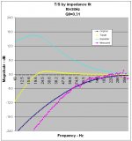
Impedance measurement, small signal: f0=38Hz, Q0=0.31
Close enough, especially if you consider that the datasheet says T/S parameters were obtained after 2h pink noise burn-in at LF at 500W. I don't have 500 W at my disposal, so no wonder the suspension never warms up enough and there are some discrepancies in the Q.
The curve fitting was the real stunner though. Below I present the "fit" of the datasheet T/S - derived, modeled FR, with actual FR measured at cone at realistic large signal drive levels (I spare you the episode where I realized that my DIY mic had bass rolloff due to the preamp input filter. Oops I just said it).
Hi Paul, how are the waveguides coming along?
I just wanted to post some peripheral info in case someone might find it useful.
When I integrated the 15ND930 to my system, I expected to do a dipole EQ and a simple shelving lowpass driver EQ to compensate for low Q driver rolloff. The dipole EQ was rather easy and measured FR corresponded well to expected values from SL's theory. For the driver rolloff, I tried several values around the expected poles as per datasheet, but things sounded rather boomier that way. So I started measuring, T/S values by impedance method in-baffle, and actual FR at cone fitted into SL's handy "box EQ" spreadsheet. SL recommends to do curve fitting of the actual FR to find the T/S parameters, because actual drivers refuse to conform to theory exactly. The results were quite revealing:
Datasheet: f0=36Hz, Q0=0.22
Impedance measurement, small signal: f0=38Hz, Q0=0.31
Close enough, especially if you consider that the datasheet says T/S parameters were obtained after 2h pink noise burn-in at LF at 500W. I don't have 500 W at my disposal, so no wonder the suspension never warms up enough and there are some discrepancies in the Q.
The curve fitting was the real stunner though. Below I present the "fit" of the datasheet T/S - derived, modeled FR, with actual FR measured at cone at realistic large signal drive levels (I spare you the episode where I realized that my DIY mic had bass rolloff due to the preamp input filter. Oops I just said it).
Attachments
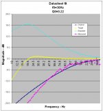
Not too bad, though around resonance and below it, the measured FR falls off much stronder than modeled. Now here is the FR modeled after the T/S data obtained by small signal impedance measurement (using DMM by hand infact). The blue curve is always the model, the pink one the measured FR which is always the same, except for vertical adjustment to get the best fit).
Attachments
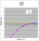
Essentially, measuring T/S data myself still gives an OK fit but we still can't fully account for actual driver behavior unless I pull out those 500 W for 2h. So, what happens if I just ignore theory altogether and do the best fit I can obtain, regardless of measured resonance or expectations of Q? Figure below.
Attachments
Soooo, conclusions?
Apparently, above driver resonance, f0 and Q - either from datasheet or from impedance measurement by myself - present a reasonable fit to the measured FR, and so the theory is vindicated somewhat.
Below resonance though the suspension seems too stiff, at domestic drive levels, to attain its spec value.
As a result the actual and "typical" behavior I can expect at domestic levels is an f0 of 69Hz and a perfect Q of 0.5, far from impedance derived expectations of mid-30's f0 and upper 0.20's Q.
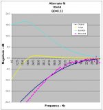
In general, this also shows that one and the same dataset can be fitted, reasonable well, to a host of vastly different f0 and Q values. Depending on what you expect to see, you'd likely beelieve any of the "fits". Below I throw in a random possible "fit" that would also pass if one was to expect these data.
In addition I will forever smile when I see people getting into heated debates of Bessel vs. LR rolloffs, especially when in fact they expect to obtain these alignments entirely by modeling box sizes after modeled FR's from impedance-derived T/S parameters. You can probably commit large errors here and you'll never know.
The conclusion for myself is actually a happy one: I expected deeper bass but unwittingly I now have a perfect Q=0.5 rolloff for free, and it works amazingly well in my room. Surprisingly I don't miss the deeper bass, it is as taut and impactful as I could wish for. I have to add that I have a strong room mode at 50 Hz, so just when driver rolloff occurs the room flattens the curve in my case, and the little content below 40 Hz or so just is not noticeable with the music I listen to. This also explains why driver compensation didn't improve the picture - wrong EQ from wrong modeling expectations, plus if I EQ the room mode does more harm than the EQ does good. I still might try to add sealed subs one day, which I can then easily blend in at 69 Hz w/o further ado or even a HP.
You never know until you measure. And that is, with several methods looking at differnet parameters.
Apparently, above driver resonance, f0 and Q - either from datasheet or from impedance measurement by myself - present a reasonable fit to the measured FR, and so the theory is vindicated somewhat.
Below resonance though the suspension seems too stiff, at domestic drive levels, to attain its spec value.
As a result the actual and "typical" behavior I can expect at domestic levels is an f0 of 69Hz and a perfect Q of 0.5, far from impedance derived expectations of mid-30's f0 and upper 0.20's Q.
In general, this also shows that one and the same dataset can be fitted, reasonable well, to a host of vastly different f0 and Q values. Depending on what you expect to see, you'd likely beelieve any of the "fits". Below I throw in a random possible "fit" that would also pass if one was to expect these data.
In addition I will forever smile when I see people getting into heated debates of Bessel vs. LR rolloffs, especially when in fact they expect to obtain these alignments entirely by modeling box sizes after modeled FR's from impedance-derived T/S parameters. You can probably commit large errors here and you'll never know.
The conclusion for myself is actually a happy one: I expected deeper bass but unwittingly I now have a perfect Q=0.5 rolloff for free, and it works amazingly well in my room. Surprisingly I don't miss the deeper bass, it is as taut and impactful as I could wish for. I have to add that I have a strong room mode at 50 Hz, so just when driver rolloff occurs the room flattens the curve in my case, and the little content below 40 Hz or so just is not noticeable with the music I listen to. This also explains why driver compensation didn't improve the picture - wrong EQ from wrong modeling expectations, plus if I EQ the room mode does more harm than the EQ does good. I still might try to add sealed subs one day, which I can then easily blend in at 69 Hz w/o further ado or even a HP.
You never know until you measure. And that is, with several methods looking at differnet parameters.
Attachments
Member
Joined 2003
Hi MBK,
For now, my activity with the DDS and MSC waveguides is complete. Below are the last tests intended to see what, if any, improvement in the MSC resulted from adding a heavy resin/sand mix to the back of the WG. (As you would expect for a $7 part, the MSC plastic is much thinner than the fairly substantial DDS.)
The MSC WGs were all modified to accept a bolt-on driver by gluing a screw-in adaptor. The (undersized) adaptors were bored out to 1" and careful smoothed to the WG profile using glass microballoons. So the plots are easy to read, microphone preamp gain was reduced to show only the first 25-30 db of decay (bottom of the scale is 45db). For reference, the DDS was measured under identical conditions. The same BMS 4552ND compression driver was used for all tests.
First the DDS...
Next the MSC with no resin...
MSC with resin and sand damping...
MSC with resin and sand damping, plus a sand texture added to the inside surface...
If anything, the sand texture on the inside of the WG seems to add HF hash, so not recommended. The resin and sand on the back of the WG seems to make a minor improvement, though it certainly isn't a dramatic change.
All things considered, I believe the modified 12" MSC is an excellent alternative to the 10x more expensive DDS. With slightly greater diameter and a little more depth, the MSC can be used a little lower in frequency...plus it delivers more consistent pattern control. Since the DDS is out of production for at least the next few months it may be an easy choice for any near-term projects.
The "bogie" is a big DIY ribbon tweeter.
Though the BMS 4552ND with WG beats the ribbon in ultimate dynamic range and, at most frequencies wins HD and IM, the ribbon sounds more natural. Dunno if it is the very quick initial decay of the ribbon, radiation pattern or what, but now I am gonna have to try a one in a WG.
For bass, I took a different approach. Since a floor is constant, the U-baffles were located outdoors on a large concrete pad about 10 meters from the nearest structure. With no reflections from nearby walls, I added just enough felt damping to eliminate the 1/4 wave U-baffle response peak and the dip above it.
With fairly "clean" driver/baffle response outdoors, they were then moved to the listening room and EQ'd for in-room response. This amounts to boost on the bottom end for dipole roll-off and two notch filters for 1.1k and 9k driver breakup modes. With an IB sub, response below 40 Hz is not as important so I didn't have to use extreme boost on the bottom end.
For now, my activity with the DDS and MSC waveguides is complete. Below are the last tests intended to see what, if any, improvement in the MSC resulted from adding a heavy resin/sand mix to the back of the WG. (As you would expect for a $7 part, the MSC plastic is much thinner than the fairly substantial DDS.)
The MSC WGs were all modified to accept a bolt-on driver by gluing a screw-in adaptor. The (undersized) adaptors were bored out to 1" and careful smoothed to the WG profile using glass microballoons. So the plots are easy to read, microphone preamp gain was reduced to show only the first 25-30 db of decay (bottom of the scale is 45db). For reference, the DDS was measured under identical conditions. The same BMS 4552ND compression driver was used for all tests.
First the DDS...
An externally hosted image should be here but it was not working when we last tested it.
Next the MSC with no resin...
An externally hosted image should be here but it was not working when we last tested it.
MSC with resin and sand damping...
An externally hosted image should be here but it was not working when we last tested it.
MSC with resin and sand damping, plus a sand texture added to the inside surface...
An externally hosted image should be here but it was not working when we last tested it.
If anything, the sand texture on the inside of the WG seems to add HF hash, so not recommended. The resin and sand on the back of the WG seems to make a minor improvement, though it certainly isn't a dramatic change.
All things considered, I believe the modified 12" MSC is an excellent alternative to the 10x more expensive DDS. With slightly greater diameter and a little more depth, the MSC can be used a little lower in frequency...plus it delivers more consistent pattern control. Since the DDS is out of production for at least the next few months it may be an easy choice for any near-term projects.
The "bogie" is a big DIY ribbon tweeter.
An externally hosted image should be here but it was not working when we last tested it.
Though the BMS 4552ND with WG beats the ribbon in ultimate dynamic range and, at most frequencies wins HD and IM, the ribbon sounds more natural. Dunno if it is the very quick initial decay of the ribbon, radiation pattern or what, but now I am gonna have to try a one in a WG.
For bass, I took a different approach. Since a floor is constant, the U-baffles were located outdoors on a large concrete pad about 10 meters from the nearest structure. With no reflections from nearby walls, I added just enough felt damping to eliminate the 1/4 wave U-baffle response peak and the dip above it.
With fairly "clean" driver/baffle response outdoors, they were then moved to the listening room and EQ'd for in-room response. This amounts to boost on the bottom end for dipole roll-off and two notch filters for 1.1k and 9k driver breakup modes. With an IB sub, response below 40 Hz is not as important so I didn't have to use extreme boost on the bottom end.
Hi Paul,
very interesting. I suspected the cheap WG was in fact the real winner, after your very first impressions. There jsut wasn't enough difference to the DDS. The CSD of your ribbons is a true stunner, that makes one think, for sure. Well, it all depends on the need for dynamics I guess. But as I noticed with my woofer experience, the proof really is in the pudding and measurements are just part of it. In fact you are lucky if you find a way to reliably measure what you already subjectively suspected or knew. I also wonder how much the CSD of the compression driver has to do with the driver itself, the compression chamber, or the horn.
I was actually laze these past weeks, except for designing CAD files (friends want to do a LeCleac'h horn, and I wanted a combo of OS WG at 120 degree coverage with LeCleac'h roundover termination). I hope I'll have the opportunity to abuse my said friend's CNC and try first my existing 27TBFCG dome tweeter on such a WG. I noticed that the actual opening of the TBFCG is 1.4" and I suspect the poor results by Zaph/others with WG on this tweeter might have come from milling down commercial WG's too much ( to fit the 1.4" diameter) so that the curvature was off. But only an experiment will tell...
Best of luck and looking forward to more of your results as they come along.
Member
Joined 2003
I wanted a combo of OS WG at 120 degree coverage with LeCleac'h roundover termination
WOW! A very interesting project that should yield excellent results. High coverage angles tend to make waveguides with good pattern control on the low end quite large. What outside diameter and XO frequency are you doing?
Well, let's say it is an experiment, with several possible implementations...
If used on a flat baffle as an insert, the WG would be ca. 14" in diameter. If using the full LeCleac'h roundover contour (as a freestanding horn) it would extend to 18". I thought I try the flat baffle insert first, and compare it to the free standing full contour. My baffle is 24" wide (o.d., 22" i.d.) so it all fits anyway.
Optically the flat baffle with horn cum woofer below it would be more simple in its looks, but a bit bulky (that is what it is now). With a smaller, say 24" square bottom just for the woofer and a free standing horn on top, it would look a bit more exotic (imagine a typical large guitar speaker "box" - they're usually open baffle anyway - with a horn on top).
In terms of X-O my minimum target is 1.2k, but ideally I'd like to reach 800 Hz. 1.2k would still allow me to use a dome tweeter, if tests turn out OK and loading is sufficient to save it from overexcursion. With the 1.4" throat, it fits perfectly the actual opening of the 27TBFCG (1" dome plus surround) that I have now. And if finances permit, I can also plug in a standard 1.4" compression driver at any time. Chances are this would actually be the preferred solution re: clarity, dispersion, and audibility of the X-O.
So in summary the horn design criteria were:
- fits my 22" internal width baffle
- allows 800-1200 Hz X-O
- has 120 degrees coverage to match a dipole's nominal -6 dB at 60 degrees off axis
- can fit 27TBFCG 1" dome or 1.4" compression driver
- can be tried on flat baffle or as a free standing horn.
I hope it's not going to turn out a swiss knife kind of thing - does everyting, but nothing really well ;-)
Member
Joined 2003
Size sounds about right 
Excluding the roundovers, can you get 1/4 wave depth at 120 degrees? What material are you going to use?
And, of course, when for pictures?
Excluding the roundovers, can you get 1/4 wave depth at 120 degrees? What material are you going to use?
And, of course, when for pictures?
Unfortunately the depth is a meager 4 inches, so this is one of the open questions: what loading, if any, can there be under these conditions. As a consequence a dome tweeter might actually work better. Then again 4"x4=16", i.e. the wavelength of 840 Hz. It might actually work...
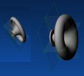
The material should be wood if I can use the CNC machine. Pics: no idea yet when this will actually get done ... but I can offer the drawing of the full roundover WG which is 18" in diameter. Due to the shallow depth one can ignore sculpting the rear side of the horn (the outside), and make the backside where the driver mounts flat - this could then simply be flush mounted on top of a flat baffle, with only the driver protruding inside the baffle.
The material should be wood if I can use the CNC machine. Pics: no idea yet when this will actually get done
... but I can offer the drawing of the full roundover WG which is 18" in diameter. Due to the shallow depth one can ignore sculpting the rear side of the horn (the outside), and make the backside where the driver mounts flat - this could then simply be flush mounted on top of a flat baffle, with only the driver protruding inside the baffle.Attachments

The 500 Hz LeCleac'h I drew for my friends is actually prettier, and smaller too (500 Hz cutoff, recommended to X-O 1 octave above). They will have a small series made in Fiberglass, and then we can add adapters for 1.4" and 1", that explains the flange.
To match the 120 degree OS WG I needed to use the edge of a 380 Hz LeCleac'h (hypex contour). But its coverage would be more like 80 degrees if I am reading the available info correctly. All this is very skimpily documented anyway...
To match the 120 degree OS WG I needed to use the edge of a 380 Hz LeCleac'h (hypex contour). But its coverage would be more like 80 degrees if I am reading the available info correctly. All this is very skimpily documented anyway...
Attachments
Member
Joined 2003
Nice CAD work...what software did you use?
It will be close. If the DDS Eng-90 is any indication, the 4" depth might be an issue...or not! The ~conical section of the DDS (which determines pattern) is about 3" deep and, as shown in the measurements above, it begins to lose loading and directional control around 1.5k. The MSC waveguide is a little deeper than the DDS and holds things together a little lower. The ribbon WG I'm working on is the same 90 degree conical section as the DDS, but 19" wide (overall) and about the same depth as the MSC...we'll know in a week or so how that works out.
It will be close. If the DDS Eng-90 is any indication, the 4" depth might be an issue...or not! The ~conical section of the DDS (which determines pattern) is about 3" deep and, as shown in the measurements above, it begins to lose loading and directional control around 1.5k. The MSC waveguide is a little deeper than the DDS and holds things together a little lower. The ribbon WG I'm working on is the same 90 degree conical section as the DDS, but 19" wide (overall) and about the same depth as the MSC...we'll know in a week or so how that works out.
I used Alibre, at some point they gave away fully functional CAD software (to better sell their "professional" versions later, but even the base version is way more complicated than I need).
Curious to see how the ribbon WG turns out. I was under the impression that the mouth diameter determines pattern control, and the depth / angle has more to do with expansion rate, and therefore, with loading. But this is my firs horn project, so I have a lot to learn...
Curious to see how the ribbon WG turns out. I was under the impression that the mouth diameter determines pattern control, and the depth / angle has more to do with expansion rate, and therefore, with loading. But this is my firs horn project, so I have a lot to learn...
Member
Joined 2003
It seems people have spent their entire adult lives studying horns/waveguides, and I now understand why...it's an addiction! Since I've only been reading for a year, I'm still a rookie, but as I understand round OS type waveguides:
* Throat geometry is primarily the means to seamlessly couple driver output to the WG wall. For typical compression drivers, this requires achieving a diffraction free 45/60/whatever degree turn. (For domes, I don't believe a turn is required...just my opinion, haven't read this about domes anywhere).
* Included angle of the near-conical section determines the radiation pattern.
* Overall size of the conical section (depth and diameter) determines the low frequency limit of pattern control...~1/4 wavelength minimum in both directions.
* Roundovers at the mouth primarily serve to reduce diffraction and reflections back down toward the throat. They also tend to frustrate builders like you and I because they are so darned large! Ideally, the roundovers are 1/4 wavelength radius.
Someone more knowledgeable is welcome to jump in, but that's the short version of how I understand it.
Well I have spent far less on studying horns, but here is how I understood it:
- originally horns were used for impedance matching - to increase power conversion from driver to air. For this one needs a slow expansion rate, so that the hard cone meets high pressure air at the throat, and has a high conversion efficiency.
- problem with classical horn equations was that they were approximations, leading to wavefronts that were not perpendicular to the side walls, thus internal reflections (plus mouth reflections, expecially when the horn is deep, due to 1/4 wave resonance). First one to propose a better wave equation approximation was Voigt, with the Tractrix
- LeCleac'h just took the old wave equations and applied them in a finite elements calculation - dividing the horn into small segments where the original equations would hold step by step, in order to get the elusive wavefront perpendicular to the side walls. The result is close to a Tractrix contour
- The loading (efficiency) issue nowadays is less acute due to high available amplifier power. So pattern control became the main goal, with again the perpendicular wavefront constraint for good sound quality. This is where Geddes developed another, more general, equation for waveguides where the loading (impedance matching) is secondary or ignored altogether, and the main element is the perpendicular wavefront constraint. Geddes later conceded that his was also an approximation, and didn't quite hold at high frequencies. But his OS seems to be the best currently available...
- So a modern waveguide should not be expected to properly match membrane-to-air impedance, for it has too high an expansion rate. There is still a dB gain in the active region though, because the space into which the now directional wave fires is restricted from the usual half-space. Say a 90x90 horn would fit 4 times into half-space, so one can expect 12 dB gain entirely due to restricted radiation space, but not from any actual loading. Therefore the amount of gain you get in a waveguide depends less on depth, asking "how well is impedance matched through slow expansion" but rather on the size of the pattern, therefore asking "to which size space are you restricting the wave and down to which frequency does this pattern control hold"
- Here I don't quite know why the wave would become directional if the mouth diameter is larger than 1/4 wavelength and progressively omni below this, but the number is close to the cut-off frequency usually given for when a pistonic driver becomes directional: at wavelength = driver circumference, i.e. 1/3 wavelength = diameter
- So this is why I believe for pattern control, only mouth diameter matters, while for additional impedance matching, or proper actual *loading*, depth, or rather expansion rate, is the key.
An additional quirk re: the perpendicular constraint, is whether the wavefront emanating from the driver is planar or spherical... the LeCleac'h worksheet has such an option to specify... but I wouldn't know how an actual driver really behaves. For instance cones are cones because the outer areas are given an intentional phase lead, to compensate for the fact that cone flex will mean that force transmission to the outer cone areas happens with a delay - the actual wavefront may well be planar, as if the cone was a true piston. Same for domes which have the voice coill on the outside: here, it is the center that needs phase lead. And of course real cone drivers usually have both - the dustcap is a dome because it is in the middle of the voice coil, and the periphery is a cone. But how about compression drivers now... what does the phaseplug do... I guess this is why eventually only ecperimentation can tell.
Member
Joined 2003
So this is why I believe for pattern control, only mouth diameter matters
I agree with most of what you say, but gotta disagree on this critical point. In Hornresp, if you simulate OS/conical flares with a constant mouth diameter and adjust depth you can see the radiation pattern change as the included angle changes. This is consistent with reading from many sources, but I think interaction with Hornresp provides the best illustration.
Seems I haven't discovered all the features of Hornresp yet - I had not seen the directivity options. Anyway so I played around with it a little.
If say I use 8 cm vs. 16 cm depth at 850 sq cm mouth which is a ca. 15" diameter mouth, the beam width angle changes of course (inclusive angle is different now if mouth size constant). The frequency at which the pattern escapes from nominal inclusive angle to full space changes not all that much, and in fact the cutoff frequency of escape is *higher* if the horn is deeper. Going down in frequency the responses actually narrow at first, before the angle escapes to infinity.
Too bad hornresp wouldn't accept a compostie of oblate spheroid cum exponential to model my proposed horn, it does segments only with conical and exponential...
Member
Joined 2003
Ahhh...terminology! I was using "pattern" to mean coverage angle, and you were talking mouth diameter determining the frequency where pattern control was lost...the wonders of E-only communications!
Yup, it would be great if Hornresp allowed mixing all of the flares, especially at the mouth. It has been a while since I tried this, but you may be able to get close to modeling your waveguide by using exponential flares. A really short exponential (Hornresp pops up a "catenoid" message) looks much like an OS flare. A second expo section may give you an approximation of the roundover...but this would be only an approximation which might spot any gross issues.
I'm really looking forward to hearing about your WG because I would also like to try a little broader coverage angle and lower frequency. The MSC and DDS WGs have me stopped at 1.2-1.5k.
Yes, it's funny how long the text can get before we convey things that could be seen in a blink of an eye...
So I tried to assemble a composite flare in hornresp to match my hand-rolled one in Excel. No such luck: Hornresp caused some really evil blue screen shutdown which I have never seen before . On retry I got a more ordinary freeze-up though severe enough that task manager couldn't help 😱 . I suppose this question will have to be answered in wood dust. I'll just have to kick myself in the rear to get moving on it. The trouble is with the many parameters that influence each other, it would be really nice to get a good handle on the guesswork, ahem, I mean the design, before resorting to major physical commitments... OTOH Hornresp would only have helped with the radiation pattern - for the actual loading and FR I would have needed many driver parameters that I can't get anyway.
So I tried to assemble a composite flare in hornresp to match my hand-rolled one in Excel. No such luck: Hornresp caused some really evil blue screen shutdown which I have never seen before
. On retry I got a more ordinary freeze-up though severe enough that task manager couldn't help 😱 . I suppose this question will have to be answered in wood dust. I'll just have to kick myself in the rear to get moving on it. The trouble is with the many parameters that influence each other, it would be really nice to get a good handle on the guesswork, ahem, I mean the design, before resorting to major physical commitments... OTOH Hornresp would only have helped with the radiation pattern - for the actual loading and FR I would have needed many driver parameters that I can't get anyway.I want to thank all of the posters for the information on this thread - the performance of the 18Sound 15ND930 compared to the Scan-Speak 8543 "audiophile" driver, the different waveguides, the little-known 18Sound near-OS waveguides, and the performance of the BMS 4552ND 1" compression driver on the two different WG's as well.
It's interesting that a big 15" pro driver working at the top of its range easily outperformed a small-diameter audiophile driver that is supposedly optimized for wideband performance - this goes against the conventional wisdom of the "right" driver for the job, and as you've posted here, raises questions about the right horn to meet the big driver in the 1~1.2 kHz region.
It's interesting that a big 15" pro driver working at the top of its range easily outperformed a small-diameter audiophile driver that is supposedly optimized for wideband performance - this goes against the conventional wisdom of the "right" driver for the job, and as you've posted here, raises questions about the right horn to meet the big driver in the 1~1.2 kHz region.
- Status
- Not open for further replies.
- Home
- Loudspeakers
- Multi-Way
- Large midrange for OB??? Scott G ?