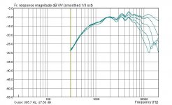
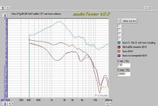
Now for some data processing for better visualisation of net horn effects. All curves obtained by substracting from each other, the dB scale is therefore relative here and correct.
Top curve, petrol: net horn loading (substract flatt baffle on-axis response from horn loaded response to get rid off FR rolloff and wiggles).
Brown curve, second from top: the difference between the tweeter at 60 degrees and at 0 degrees, on a flat baffle. Nothing unusual here.
Bottom two curves: with and w/o faceplate, horn mounted tweeter, difference between 60 degrees and 0 degrees. This shows the net *directivity* effect (as opposed to the net *loading* effect above).
Comments:
On the bright side, loading achieves ca. 9 dB around a peak at 1.6k and still manages about 6 dB at 800 Hz in spite of the just 100 mm deep horn. Also, directivity is maintained well down to 900 Hz (-5 dB at 60 degrees) with -7 dB / 60 at 1.6K maximum.
The directivity at 60 degrees is however a bit lumpy. WHile the expanded dB scale in this picture exacerbates this, I also suspect that the dome tweeter simply really is not cut for horn / WG use. Judging from the loading differential in faceplate / no faceplate compariosn, a ca. 1 cm high dome stiching into the throat area probably does not provide the called for waveform at the throat. Compression drivers assure this via their sophisticated phaseplugs.
So conclusion, this size horn best until 1k, and likely useable down to 800 Hz; detailed investigation of off axis behaviour should be done with a compression driver.
Attachments
Hi Paul,
don't want to do you in to jump the gun, but if you're interested in the BMS4590, here is a special offer, returned from customer:
BMS4590 special offer
Thinking about the WG's you are right - by calculation and extrapolation a 18" WG shall be required to truly make it down to sub-800 territory.
don't want to do you in to jump the gun, but if you're interested in the BMS4590, here is a special offer, returned from customer:
BMS4590 special offer
Thinking about the WG's you are right - by calculation and extrapolation a 18" WG shall be required to truly make it down to sub-800 territory.
Hi Paul,
curious what you conclude so far from Earl Geddes' contributions to various threads... it's great that he put out quite a bit of info to the public in such a short time frame.
For myself on the bright side a 1" driver seems to be capable of putting out pro level SPL in a WG down to sub-1000 Hz territory. That makes things a lot easier - better HF response for instance - and cheaper. And mouth diffraction seems to be less of an issue than HOMs, so maybe the mouth termination at least won't eat major experimentation time.
There seems to be some complications too compared to my initial simple assumptions:
- foam plug seems to be definitely advised
- no way of easily measuring HOMs with standard tools
- drivers' exact exit diameter and angle matters (plus different drivers with different phase plug gometries may or may not produce planar or spherical wavefronts to varying degrees).
So this all means horn experimentation really ought to be done with the specific driver one wants to use, with special attention to the throat which will have to be modified from a standard spreadsheet derived oblate spheroid shape.
Thinking all this over the 18Sound ND1020 caught my eye. 1", very low compression ratio (1 1/3" voice coil), phase plug optimized for their own CD horns (and if you download some of the recommended the horn datasheets you clearly see that the throat profile does not start at 0 degrees!). All for <100 USD it seems. Of course there is the Ueber-NSD1095N as well with the coated titanium diaphragm but I am sure this one will be 3 times the price.
I still am in the wider dispersion camp though, so I still want to go the 120 degree coverage route. Looks like another horn prototype is in order though, and maybe with a variety of different throat sections. Ugh.
And, my data still need to get cleaner. 🙄 Although I think much of my prototype's deviations from "true" CD is due to the dome driver with its unpredictable wavefront shape.
Looks like another horn prototype is in order though, and maybe with a variety of different throat sections.
This prompts me to consider detachable throat sections. A joint in the conical section might be the most benign, with care given to joint match-up, of course.
MBK, good catch on the 18Sound ND1020 and NSD1095N compression drivers. Notwithstanding the narrow dispersion, they might sound pretty good on the XT1086 horn. Don't forget that if the intended application is a dipole system, the option of a rear horn remains open.
There's two pluses to a rear horn: they have narrower dispersion than dome tweeters, resulting in less "splash" from the rear to the front, where it could degrade imaging. The other plus is that a rear horn doubles the energy into a sphere, bringing the total-energy room curve much closer to the on-axis curve. This would be subjectively audible as much wider dispersion, a more "open" sound than usual for horns.
Another aspect of a rear horn is the location of the compression driver - it'll end up being fairly close to the front baffle, since you want to line up the diaphragms of both front and rear horns (for equal path lengths exactly 90 degrees off-axis) - and reasonably good crossover integration on the back side of the dipole.
This prompts me to consider detachable throat sections. A joint in the conical section might be the most benign, with care given to joint match-up, of course.
Ed,
that's actually what I meant, a flare end and various replaceable throat ends, mated somewhere 2" into the total horn depth where the profile is a straight line and any microscopic ridge from improper mating can be sanded out by hand. And then it's much easier to produce a series of small throat-pieces with varying angles of entry and diameters if necessary, and they all mate with the same (literally) mouthpiece, same flare etc. Should be good for comparisons.
Lynn,
trouble with 18Sound's own horns is the narrow dispersion angle. To meet a dipole or cardiod's power response the angle should be roughly 120 degrees axial symmetric. I currently tend towards trying cardioid on the woofer (thus one front horn would be enough to mate LF and HF radiationpatterns). I though of using felt, like Paul here, and I also thought of some schemes similar to the ones mentioned in your thread - stached meshes of different mesh sizes, and / or approaches similar to muffler / jet engine exhaust damping.
But I haven't done any experiments yet, I still want to get my measurement capability to improve enough so I actually trust what I measure.
The really big advantage of say an ND1020 is that you don't have to mortgage the house to try one so you don't have to be virtually certain of the "experiment's" result *before* you buy. 😱 And, it looks like a very good unit - actually it's 18Sound's only HF driver touted as "for the *highest* possible sound quality systems". All others get a "for *high* quality..." rating. FWIW, haha.
Member
Joined 2003
MBK,
Yes, there is a lot of information flowing. Earl's patent applications and AES papers have been available for some time, so the discussion now really helps fill my gaps in understanding. Some of the information is the same thing stated differently, but it is still extremely helpful. Other clues, like the 6.5 degree exit angle, was completely new news for me.
My main problem has been identifying HOMs but I believe Earl indicates they should be visible in CSD plots. I need to spend more time combing through those plots, maybe change time scale, etc. Unfortunately, I don't have time to do this now.
Perhaps one reason I'm having such a hard time "seeing" HOMs is that I'm using a happy collection of parts...the DDS is very close to an OS and even the (round) MSC has to be better than a square or rectangular WG in the HOM department. Also, in reading patent 5878148 (BMS) relative to patent application 20060034475 (Geddes) it seems BMS achieves many of the same advantages over a "standard" compression driver...though for different objectives and by a very different approach. Perhaps HOMs would be more obvious with "standard" parts.
You, Ed, and I are on the same page with a modular WG. My current thinking is a large conical WG, flat 4-6" throat, with threaded studs or inserts to mount the actual CD/WG throat section. Since throats are so critical, building several 4-6" WGs will be much more practical than starting from scratch every time...plus, I can justify purchasing a small lathe🙂
Other than TAD and the like, I'm leery of 1" drivers significantly below 1k. (Note how close FS is to 1k on the 18Sound 1" drivers.) My experience so far makes me believe distortion will rise if a 1" is pushed hard below 1k. At least the combination of WGs and the 4552 seems to be completely out of gas at 1k...of course I won't know for sure until I build a larger WG. On the other hand, I believe what Earl (wasn't) saying is that the 1.4" drivers do not have enough HF output (w/passive XO) to overcome the losses of a foam plug.
Thanks for the link to the BMS 4590s. That really is a great price! Unfortunately, it will be some time before I get to the WG portion of this project so I don't want to take a chance with "B-stock" parts...could get too messy later.
I wouldn't be too quick to give up on the WG you have now. Just because a dome is not working as well as you want doesn't mean the same thing will happen with a compression driver.
Paul
You have a point re: 1" or 1.4". From specs I always assumed 1.4" to be the ticket. Now it seems Earl has no problem with a 1", but, but, for once his WG is narrower than my target and that means he gets more lift, just by restricting the power into a narrower angle, and subjectively my experience with my 15" woofer suggests that there really is no replacement for displacement... And with active XO and multi-amplification which I have anyway there is a lot more freedom of choice than Earl has with his passive approach. OTOH 1" drivers are a lot cheaper and their breakup tends to be far out near 20k, so it's tempting to believe that it would work out ok.
I was looking at a lot of driver specs lately, and in the 1.4" department my current favourite idea of price perfomance is the RCF ND2530T3 . It is quite a bit cheaper than the top 18Sound drivers and has more droop at the high end, but if you look at the FR carefully (in the pdf data sheet) it is exceptionally regular, and there is a curious absence of the peak in the 13k-17k region that almost all other 1.4" titanium drivers display, and also less FR wiggles in that region. Their other drivers' published FR are not nearly as clean there, so I assume it's not simply because they over-average. Also, this one has a 2.5" diaphragm, thus lower than typical compression ratio.
BMS another thing - the coaxial CD, what I don't get is how they advertise 300 Hz lower limit. From the FR it drops like a stone south of 600-500 Hz, more like a typical 1.4" driver. Also the FR of both components, nevermind the one with the passive XO, ist not all that smooth either. Ah well, I guess with EQ everything can be fixed...
HOMs, phaseplugs etc... seems many manufacturers have patents on their own solution to the problem, 18Sound too, question is always which works best in the end and with which WG...
My WG will see some other tests - first a replay with the Vifa, to get cleaner data. Then I still have my Seas 27TBFCG though I am loathe to cut them out of their rubber seal in my main system where they are playing daily. And hey maybe I find someone locally to lend me a 1.4" driver.
Time , yes... I am currently also building 8 channels of amplification, a DIYAudio "product", tired of my chipamps of which one channel keeps on clipping at progressively lower SPLs with no discernible reason. Plus house projects etc. So all this explains my leisurely pace...
MBK posted:
question is always which works best in the end and with which WG...
I think you nailed it right there. A guide that works well with one CD may not be as good a match with another.
Member
Joined 2003
I was looking at a lot of driver specs lately, and in the 1.4" department my current favourite idea of price perfomance is the RCF ND2530T3 . It is quite a bit cheaper than the top 18Sound drivers and has more droop at the high end, but if you look at the FR carefully (in the pdf data sheet) it is exceptionally regular, and there is a curious absence of the peak in the 13k-17k region that almost all other 1.4" titanium drivers display, and also less FR wiggles in that region.
I haven't read many comments about RCF drivers. As you say, it's curious the HF FR falls off so far...the impedance is still low at 20k. Maybe the horn???
I've been reading some negative comments about titanium drivers...and not just from the fans of drivers available only in aluminum. Some of the comments drill down further, ascribing the poor sound to the titanium surround rather than the dome. Dunno if the surrounds are "oil canning" or what. Did you see any good looking titanium 1.4" with a non-titanium surround? One "hot rod" combination might be the ND1480 motor (high flux density) with the ND1460A dome (aluminum dome/polyester surround). Total cost with two sets of domes might be about the same as the 1480 with the titanium nitride domes.
BMS another thing - the coaxial CD, what I don't get is how they advertise 300 Hz lower limit. From the FR it drops like a stone south of 600-500 Hz, more like a typical 1.4" driver. Also the FR of both components, nevermind the one with the passive XO, ist not all that smooth either.
What is also surprising is that some guys are using the BMS coax at 250-300Hz! BMS charges only about $10 for the passive crossover, but the low cost is reflected in the performance. I'd rather BMS offer a high quality crossover and charge accordingly and/or publish the schematic for a quality crossover...the one they are selling has to be hurting their reputation.
And hey maybe I find someone locally to lend me a 1.4" driver.
That would be great! Especially if it is a driver with known performance. Maybe try for a known driver on a known horn to give you a control reference???
Paul W said:
Some of the comments drill down further, ascribing the poor sound to the titanium surround rather than the dome.
A very WISE observation!
It isn't just the surround though, but the surround is probably a greater factor. (..in fact its a problem in most drivers.)
If you *must* have well spec.ed drivers.. that 18 sound ND2060A looks pretty good.
If you want good sound and are willing to work with the driver (and still except some faults) - this midrange is a bargain:
http://www.google.com/search?hl=en&q=selenium+d405_i&btnG=Search
Isn't that purported titanium problem maybe just an issue of metal dome brakup modes, which the typical pro XO ignores and the typical passive home XO isn't capable of tackling? Metal cone midranges also had / still have a "reputation" but with proper EQ nowadays there's less and less comments of the "metal sound" kind of stereotype.
When I look at typical titanium drivers' FRs I see a shelf developing past 10-13k (for a 1.4" exit, 3" VC), with abrupt breakoff at say 16k or so. The shelf makes the response look flatter, more HF extended. In fact I think it's a breakup peak that masks the natural rolloff the driver would have. This is why I found the RCF2530's curve interesting, because it looks like what you'd expect in a natural bandbpass behaviour, *without* the breakup-induced shelf, hence it looks like it droops earlier at HF. My point being, Precisely that it droops makes me think it has less breakup issues.
If you look at 18Sound's untreated vs treated (polyimide film) titanium drivers, the former have clear breakup peak, the latter have this peak broken up and subdivided into a larger, but flatter, region of breakup. But in the RCF2530T3 I don't see any breakup at all.
Just half-witted guesses...
Member
Joined 2003
Isn't that purported titanium problem maybe just an issue of metal dome brakup modes, which the typical pro XO ignores and the typical passive home XO isn't capable of tackling? Metal cone midranges also had / still have a "reputation" but with proper EQ nowadays there's less and less comments of the "metal sound" kind of stereotype.
The straight answer...I don't know. The discussions I saw (AA and DIY-A) were not "metal" vs plastic, but titanium vs aluminum vs plastic. Titanium, and sometimes more specifically titanium surrounds, were cited as the bad guy...not "metal". There is at least one patent that mentions aluminum as better "internally-damped" than titanium. I'll try to find it if you want, but dome material wasn't the point of the patent.
When I look at typical titanium drivers' FRs I see a shelf developing past 10-13k (for a 1.4" exit, 3" VC), with abrupt breakoff at say 16k or so. The shelf makes the response look flatter, more HF extended. In fact I think it's a breakup peak that masks the natural rolloff the driver would have. This is why I found the RCF2530's curve interesting, because it looks like what you'd expect in a natural bandbpass behaviour, *without* the breakup-induced shelf, hence it looks like it droops earlier at HF. My point being, Precisely that it droops makes me think it has less breakup issues.
That is entirely possible. Maybe the smaller 2.5" dome is a "sweet spot" just below the breakup of the 3" domes. Is there enough info out there to compare moving mass or dome thickness?
I looked up the 2530 on one US site ($249) and they highlight "smooth, warm, highs".
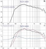
What I usually do is I take the mf's FR graphs, resize them and overlay them to exact scale. Oftentimes I get surprises because the varying scales ppl use can make for the wrong impression. For instance here below is what I mean wrt breakups:
- top, NSD1480N overlaid on ND1480 taken as "standard titanium". Clearly visible is that the NSD's coating dampens a garbled breakup (thanks, 1/3 oct averaging!) at 7-12k, and a peak at 16k, and makes them more benign.
- bottom, ND2530T3 over said ND1480: no rise between 7-12k in the first place, and only a hint of a peak at 16k. Past 16k, identical curve save for sensitivity. Also interestingly, past 5-6k the ND2530T3 rolloff is almost perfect 6dB/oct. I would have said voice coil inductance, but the ND2530T3 has a copper ring. What gives...
All graphs vertically adjusted for same max SPL because this likely depends on horn type. All graphs were on 80x60 horns but RCF's horns are these squarish, brutish things and it looks like the 3k dip matched with an impedance irregularity, as well as the lesser low end loading of the ND2530T3, are a result of a different horn. On the same horn I'd expect it to have a broad loading maximum around exactly 3k where now we find that dip.
Attachments
Dear Paul W and MBK,
earlier in this thread (posts 284 and 290), you have both proposed rather large diameter waveguides (28 inch respective 21 inch).
I understand that you are planning to use your waveguides with 1 inch driver. If my understanding is correct, and assuming that you will not try to use the driver/waveguide below 800 Hz, will the center-to-center distance to a driver handling frequencies below 800 Hz not cause problem with the pattern resulting from the combination of the two sources?
Thenk you,
M
Member
Joined 2003
I plan to first use a larger WG with a 1" but then probably move on to a 2" coaxial driver. Yes, I expect lobing at crossover due to the longer than desired CTC distance, but it is a compromise I am willing to make for lower distortion and radiation pattern control over a wide range. To minimize the CTC effect, I will use 8th order XO for narrow frequency overlap.
Hi M,
Actually the size of the HF driver is not the issue, it's just that the x-o frequency is more or less constrained by the waveguide size (that is, if you want the directivity patterns to match).
The physics that make a waveguide work (that make it beam so to speak) are the same physics that make a cone driver beam. In other words, a waveguide will stop beaming (stop being a waveguide) as you go down in frequency roughly at the same point as a cone midrange will start beaming (stop being a piston) going up in frequency, and this will be around the frequency where diameter = wavelength. Around this point will then be your x-o frequency because at this frequency the "beaming" patterns will roughly overlap (dispersion will be similar) and your CTC will be one wavelength, just the upper acceptable limit for driver spacing.
Dear MBK,
thank you for the answer.
You wrote: "Actually the size of the HF driver is not the issue, it's just that the x-o frequency is more or less constrained by the waveguide size (that is, if you want the directivity patterns to match)."
My point in reciting a size of an HF driver was to illustrate that due to insufficient loading by the waveguide, most modern 1 inch drivers could not be expected to provide sufficient output much below 900 Hz. This corresponds to a wavelength of about 15 inches.
Consequently, if your waveguide has a mouth diameter of 21 inches and assuming 15 inch driver, the center-to-center distance is at best 21/2+15/2=18 inches.
Hence my question about resulting pattern.
MBK: "The physics that make a waveguide work (that make it beam so to speak) are the same physics that make a cone driver beam. In other words, a waveguide will stop beaming (stop being a waveguide) as you go down in frequency roughly at the same point as a cone midrange will start beaming (stop being a piston) going up in frequency, and this will be around the frequency where diameter = wavelength."
This is not my understanding; could you please provide some references?
MBK: "Around this point will then be your x-o frequency because at this frequency the "beaming" patterns will roughly overlap (dispersion will be similar) and your CTC will be one wavelength, just the upper acceptable limit for driver spacing."
Assuming that the patterns will be the same, my understanding is that although a necessary condition this is not a sufficient condition for the resulting pattern be the one of the individual drivers unless brick-wall filters are used and the patterns are alligned at (one) listening position. After all, there is an offset between the drivers.
Or am I missing something?
Thank you for your help.
M
- Status
- Not open for further replies.
- Home
- Loudspeakers
- Multi-Way
- Large midrange for OB??? Scott G ?