2" inner coil dia the final coil would have an outer diameter of 7.49"
If you already have an iron core choke I saw an idea that wouldn't be
hard to try. That is put a small aircore inductor in seriese with the iron core
choke. I noticed someone did this in an old single ended OTL where they
used perhaps a 10mh aircore inductor in seriese with a 500 mh iron core
inductor.
I can easily imagine that resistors might sound better if the CCS is not performing correctly. A two stage CCS can perform extremely well though! I advise using an empirical approach to setting the value of the drain resistor that ties to V-.Dear Atma, active CCS will certainly improve voltage swing headroom (and power handling of the output) but, will it sound better? I tend to prefer passive CCS, in fact the inventor of the circuit -ECdesigns- made extensive test with different configurations and decided that this one was better soundwise.... but I will try a cascoded CCS sooner or later. In fact my next move will be cascoding the VFET, as I am a very big fan of cacoding the output, as my new signature suggests.
I find that the best approach is to set the value such that when the gain stage is overloading, that the clipping is symmetrical. Beyond that you want it to allow the maximum gain, so long as that does not interfere with the clipping character.
BTW, this may eliminate the need for the balancing potentiometer. If not, it is advisable to make that part the lowest value to do the job as it degrades the performance of the circuit.
Have fun!
I can easily imagine that resistors might sound better if the CCS is not performing correctly. A two stage CCS can perform extremely well though! I advise using an empirical approach to setting the value of the drain resistor that ties to V-.
I find that the best approach is to set the value such that when the gain stage is overloading, that the clipping is symmetrical. Beyond that you want it to allow the maximum gain, so long as that does not interfere with the clipping character.
BTW, this may eliminate the need for the balancing potentiometer. If not, it is advisable to make that part the lowest value to do the job as it degrades the performance of the circuit.
Have fun!
OK.
Thank you very much.
M.
Hi Soundhappy,
SE version. Its taken from my previous SET amp project
Surya
Hi Surya
Ok do you try experiment ?
Respect (-)(+)phase dots
Greetings 🙂
Not yet with SK180.
Sure phase is correct refer to Lundahl datasheet
Bests
S
Sure phase is correct refer to Lundahl datasheet
Bests
S
Hi Surya
Ok do you try experiment ?
Respect (-)(+)phase dots
Greetings 🙂
I ready try auto-bias KD-33 version with 12 ohm resistors in serie
my conclusion with bias circuit is better amp
My conclusion is different, self bias is better one. but I use 30Vds(from 25Vac and 1.6R choke) and 4ohm bias resistor with 1.7A flows on it
Attachments
Last edited:
@ Gadut
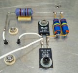
I like it very much your version.
Short point to point wiring close to vfet.
Kindest regards
I like it very much your version.
Short point to point wiring close to vfet.
Kindest regards
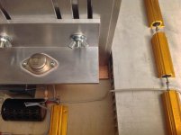
At the risk of sounding rather thick, how does this work? I can see how simple the circuit is but how is the negative half of the wave amplified when there isn't a complementary device?
Also, why does it need such a huge heatsink? I can see the bulbs are about 22r and ~2A current, but they can cope with that in free air, and the heavy duty 1r resistor is going to be 2W or so, and that appears not to need to be on the HS. The FET needs to stay cool of course but I've seen less cooling on medium sized motorbikes.
Also, why does it need such a huge heatsink? I can see the bulbs are about 22r and ~2A current, but they can cope with that in free air, and the heavy duty 1r resistor is going to be 2W or so, and that appears not to need to be on the HS. The FET needs to stay cool of course but I've seen less cooling on medium sized motorbikes.
It's a single-ended circuit biased at the maximum peak current. The
"complement" to it is a resistor. Not efficient, but works fine.
"complement" to it is a resistor. Not efficient, but works fine.
Thanks, that's getting the answer from the horse's mouth! I understand that it's biased to max current but I'm sorry, I still don't see how if the -ve terminal of the speaker is attached to earth the +ve terminal can be drawn to a negative voltage. Sorry, I realise this is the sort of thing you do in your sleep.
Aah yes, I see now. So the sine wave is expressed as a permanently positive wave around some arbitrary floating central point. Got it.
You could do worse than read Nelson Pass's articles on his passdiy site about how a simple one stage single ended amp stage works. They completely cover your questions.
Thanks Protos, I'll do that. My understanding of amplifiers is limited, beyond being able to decode a schematic and understand basics like voltage dividers and Darlington Pairs. I shall read Hartley-Jones on amplifiers again as well, that can't do any harm.
Edit, thanks also (to someone else) for the PM talking about heat dissipation in Class A designs, and the direction to the Pass site. There's some stuff on there to read. It's almost like this Nelson Pass chap knows a bit about amplifier design. He knows quite a lot about electronics, at least.
Edit, thanks also (to someone else) for the PM talking about heat dissipation in Class A designs, and the direction to the Pass site. There's some stuff on there to read. It's almost like this Nelson Pass chap knows a bit about amplifier design. He knows quite a lot about electronics, at least.
Last edited:
is this the end ???
BUMP !!!
i want to post something, but no idea, so let me bump this great amplifier.
after increasing my dac output to 3V instead of 2V, now i dont need any extra preamp yet and ended with volume control around 12 - 13 o'clock.
so my question to all SIT builders, i know this is not your only diy amplifier, there must be others. What do you do with them which are unused?
my first diy class a : alephj, i got a barter the board with my friend, he build me heavy base for my OB.
m2 & j2, both have their own case, dont know what to do with them, just laying around on the corner. I had a thought to disamble them, tried to build class ab or other class a amplifier, but will it 'beat' the '2' series or L'amp? does the effort worth it?
or just say : it's enough? 😕
make universal PSU with umbilical , then buy bunch of heatsinks , and make all your future amps as modules
enough was long ago , everything after that is fun ........ so why not 🙂
enough was long ago , everything after that is fun ........ so why not 🙂
make universal PSU with umbilical , then buy bunch of heatsinks , and make all your future amps as modules
This is also my idea. But need lot of time and more hardware to put into practice.
make universal PSU with umbilical , then buy bunch of heatsinks , and make all your future amps as modules
enough was long ago , everything after that is fun ........ so why not 🙂
This is basically what I have done. Great experimental platform 😀
On the left at bottom is 22V PSU with M2 (in test mode - just added 2SK1530 / 2SJ201 ) and Funny F6 (per Justin Forbis) above
On the right is 27V PSU with VFet2 above
Best
Bob
Attachments

- Home
- Amplifiers
- Pass Labs
- L'Amp: A simple SIT Amp