any schematic somewhereof this pseudo parafeed trick ?
Tons of it on the interweb. Google Tube Cad Parafeed
Unfortunately, as you look around you see all sorts of circuits referring to
parafeed which largely have one thing in common - the load is cap
coupled from the Plate/Drain/Collector to the Cathode/Source/Emitter
pins of a single-ended gain device.
Tube Cad does give a nice example showing push-pull circuits which don't
meet that definition except in effect. I can think of a couple others.
As there is poor consensus on what constitutes "parafeed", probably
"pseudo-parafeed" just means "no tube / no transformer"
😛
I posted my sketch of this on this thread a few months ago. Been listening to this layout off and on since then.
I termed it pseudo parafeed because as Nelson states, there's no transformer. The speaker coil is playing the part of the more typical parafeed output transformer primary you'd see in a tube parafeed.
I did try a full parafeed arrangement - choke plus output transformer - but found it less "direct" and "live" sounding.
I gave references to some Lynn Olson and Paul Joppa articles on the various ways to configure a parafeed stage. I used what's called in the Tube arena the Western Electric or WE style where the load is returned Via a cap to the cathode (source). This eleminates the need for a traditional bypass cap across the self bias resistor.
I've been told there is a risk of increased PS noise in this config but I haven't heard it. WE used a workaround for this way back when which looks odd to modern eyes. The used an additional cap across the load scaled to the main cap according to the mu of the tube so that a small amount of out of phase ps noise is introduced at the cathode.
I haven't tried that since I didn't need it.
I have noticed that the simpler the speaker, the better with this amp. My full range drivers are great, the tannoys excellent but my son's modern bookshelf speakers are pretty dull with this amp.
I just realized that my speaker cone move out when turn on, I measured that Vdc increase up to 1.6V then decrease significantly. Did not notice it since no any thump sound. Same with turn off but opposite direction with smaller movement. below video its movement during on/off
https://youtu.be/niCtQgjpcSc
is it safe for speaker coil eventhough there is no 'dug' sound? Cout value should be 10mF for my 300mH choke, but now I only put 4700uF. I have also tested by adding another 10.000uF but now the cone move more.
I'm thinking to add speaker protection with delay 3sec but is it safe for SIT if no any speaker connected?
a 8r in that 3sec😛 or just put a caps then bypassI'm thinking to add speaker protection with delay 3sec but is it safe for SIT if no any speaker connected?
if you're going to use speaker delay , be sure to have ,say, 47R/3W prior to relay (permanently connected) , to ensure DC path for cap charging
that's it - cap charging current is inducing that thump , same as discharging, when powering off
however , if it's not audible (as you say ) I believe there is no so abrupt current involved ........ so leave it as is
that's it - cap charging current is inducing that thump , same as discharging, when powering off
however , if it's not audible (as you say ) I believe there is no so abrupt current involved ........ so leave it as is
Thanks ZM, I'm less worried now not to burn the speaker. even on my video, there is a 'click' sound of AC switch plus my child background noise, but no thump.
I might need to find speaker protector kit with relay + fixed resistor. If i remove speaker load completely, i think that 19V on SIT drain will be converted into heat of its 1.2ohm Rds 🙂
I might need to find speaker protector kit with relay + fixed resistor. If i remove speaker load completely, i think that 19V on SIT drain will be converted into heat of its 1.2ohm Rds 🙂
no, wrong , nothing to worry about SIT
what I'm trying to say - even if you delay speaker connection , if there is no other DC path for cap charge , you'll get thump again ....... just delayed
what I'm trying to say - even if you delay speaker connection , if there is no other DC path for cap charge , you'll get thump again ....... just delayed
I'm keen to get an idea of "risk" here - so bear with me.
The house I am in has had the powersocket I am using throw the breaker at least once in the past 6 months for no reason that I can see (could have been a big load in another room, Im not sure).
However what I want to address is this - If both powersupplies (main and bias circuit) are connected to the same powerpoint, and the power goes off - will there be enough time in the time it take for the main circuit to discharge, to ensure that the VFET doesn't get damaged? My thoughts would be that the main circuit would take a lot longer to discharge due to the bigger caps (compared to the bias circuit). Is there a danger here? I was even thinking of running the bias circuit only thru a small UPS to address this - but I would rather not bother? thanks!
There is another powerpoint in the room and I haven't checked to see if it is on another circuit (and using another breaker) but lets assume they are on the same circuit/breaker at the moment.
No worries here, since zero bias will be a problem only with choke-drain-loaded model. With CCS or resistor biased SIT models, these components will limit the maximum drain current, and one can delay the bias supply (with big R-C) to have zero bias when starting the amp and avoiding the turn-on thump a little, since with zero bias we have a "closed switch" with SIT.I'm keen to get an idea of "risk" here - so bear with me.
The house I am in has had the powersocket I am using throw the breaker at least once in the past 6 months for no reason that I can see (could have been a big load in another room, Im not sure).
However what I want to address is this - If both powersupplies (main and bias circuit) are connected to the same powerpoint, and the power goes off - will there be enough time in the time it take for the main circuit to discharge, to ensure that the VFET doesn't get damaged? My thoughts would be that the main circuit would take a lot longer to discharge due to the bigger caps (compared to the bias circuit). Is there a danger here? I was even thinking of running the bias circuit only thru a small UPS to address this - but I would rather not bother? thanks!
There is another powerpoint in the room and I haven't checked to see if it is on another circuit (and using another breaker) but lets assume they are on the same circuit/breaker at the moment.
But for choke-loaded model I prefer to use a fast turn-on bias supply, to avoid damaging the SIT.
I'm sure that SIT will survive when negative bias is gone and B+ is still in process to decrease. Based on my observation, B+ will be eaten by SIT less than 2sec. You can monitor B+ will led brightness or music which slowly fade off.
I had been stupid to connect the bias with positive supply more than 1 time and more than several second 😀 of course there was no smoke. SIT is one tough guy
I had been stupid to connect the bias with positive supply more than 1 time and more than several second 😀 of course there was no smoke. SIT is one tough guy
Sweet - thanks for that. Just to confirm - I do have the version with the V193, I keep the bias supply powered-on constantly with its own powercord, and only power the B- supply (I have a 2SJ28 amplifier) on and off with a switch. But your response makes sense gadut given what appears to be the high power consumption of the transistor.
Hi everybody!
first of all i would like to say thank you to everyone

=================
I've built Ironamp and i love it than any amp i've heard(except Sony P.2 😀).
But It's nature sound make me wonder how is really Vfet'sound because I don't believe in my diy OPT 😀 .... so I decided to build L'amp, the same with cap output.
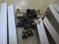
and there are resitors and choke I have for L'amp.
and my questions : with 15omh R load Ver. or 4.5rDC/0.8H-1.5H choke load ver. what Vsupply, Vds and Ids seem be G point if I use 2SK82 KE-33 vgs 7.0 or 2sk180 😕
Tks & Rgds,
Jahamvui.
Attachments
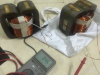
What is the max amperage rating of the choke? I am afraid that 4.5R choke might not fit to the high current circuit.
Tks plasnu! I think you're right if I use it as choke input in LC filter.
By the limits of the window, wire size = 1.40, DC current max = 4A. So I hope my chock will be safe and not overheat if i use it as choke load and Ids somewhere in between 1.7A-2.0A.
By the limits of the window, wire size = 1.40, DC current max = 4A. So I hope my chock will be safe and not overheat if i use it as choke load and Ids somewhere in between 1.7A-2.0A.
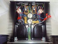
Hi there - here is my build - about 90% complete.
However rather typically, I got to this point and only then thought about any effects from the close proximity of the V193s. Its a small box and relocation would be a real PITA. As it is, the power trafos are already located outside the box.
Any thoughts on this? thanks!
However rather typically, I got to this point and only then thought about any effects from the close proximity of the V193s. Its a small box and relocation would be a real PITA. As it is, the power trafos are already located outside the box.
Any thoughts on this? thanks!
Attachments
Also - should I be getting the full bias voltage at the RCA-end of the input capacitor? Even under load? I have completed my build and am getting a hum/buzz once RCA's are connected to a sound source. Not sure at this point if its a grounding or powersupply issue.....thanks
Hmmm... if one measure the input side of input cap with a normal multimeter, will measure the bias for several seconds. but with source connected... is less probable, unless source is cap-coupled, and for sure the voltage will change. is good to check if capacitor is not leaky, or if have some wiring shorting or solder splashAlso - should I be getting the full bias voltage at the RCA-end of the input capacitor? Even under load? I have completed my build and am getting a hum/buzz once RCA's are connected to a sound source. Not sure at this point if its a grounding or powersupply issue.....thanks
If source is buzzing, you can disconnect the input cap and short them at amplifier input ground, for checking if source is noisy (aka. connecting only source "GND" and ignoring signal).
If buzzing persists, some grounding check are in order. Is possible to have some wiring/routing less than ideal or even the source, or ground loops. Is sometimes difficult to locate, but possible if observe all signal grounding routing rules (yes, confusing to newbies and even for experienced ones if circuit is complex)
Hmmm, I'm starting to think my main power supply isn't that clean. I'm using 2 NOS C-Core transformers (not built for audio) that I'm stepping down thru another powersupply. So; too many powersupplies in the chain and probably not all that "clean." I will sub these out for a new single Antek trafo that I can plug directly into my wall supply and try again.
- Home
- Amplifiers
- Pass Labs
- L'Amp: A simple SIT Amp