Another dumb question sorry - I have power transformers that each have a 35VAC secondary (note there is no centre tap). That will rectify to around 50VDC. That may be twice as much voltage as what I need for the Hammond circuit? Will that voltage be excessive and if so, can anyone recommend a DC-DC stepdown suggestion that will handle the required current? cheers
One "extremist" but easy solution is to use the 220V trafo in 110/120/127V mains***** or a "adapter" transformer (such one to adapt the voltage to foreign electric appliances). With 120V at one 220V trafo, if the original secondary is 50V will be ~25V or so with the reductionAnother dumb question sorry - I have power transformers that each have a 35VAC secondary (note there is no centre tap). That will rectify to around 50VDC. That may be twice as much voltage as what I need for the Hammond circuit? Will that voltage be excessive and if so, can anyone recommend a DC-DC stepdown suggestion that will handle the required current? cheers
If you have one such adapter trafo with proper power ratings, you can use
Some advantage appears: with low primary voltage, the trafo will operate with low induction and will make less noise, stray magnetic fields and core heat
*****or a 120V trafo with a 220V/110V adapter entering 120V at "220V" in so results in more or less half of mais voltage at "110/120V" output (eg. 65V)
Or unwind turns at secondary until reaches the desired voltage
Last edited:
Another dumb question sorry - I have power transformers that each have a 35VAC secondary (note there is no centre tap). That will rectify to around 50VDC. That may be twice as much voltage as what I need for the Hammond circuit? Will that voltage be excessive and if so, can anyone recommend a DC-DC stepdown suggestion that will handle the required current? cheers
...you should´ve waited a few days before ordering your tranny...
 - 😀
- 😀easiest way would to sell the tranny here in the swap meet and buy
another one with appropriate voltage.
...or you could get brave and try a choke loaded PSU, this will drop your
voltage to the needed value, you need much smaller capacitors and its
much less stress for the tranny.
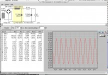
do you know PSUD2 ? it´s a very smart little piece of software, i play
with much too much.
i´ve done a quick simulation for a LCRC-Filter with the Hammond 159ZC
that should work for you.
cheerio,
Balou
Attachments
Thanks guys - I have a 100-120VAC adjustable 2000W stepdown - I will use that, seems like a good solution!
Yet another dumb question - I think I will go for the resistor version first - gets around the lightbulb issue and cheaper than the Hammond choke.
Is the secondary for the main powersupply feed either 40VAC, or 28VAC for this version of the circuit? I will be using 1 x 12 ohm 100/W resistor in place of the bulbs.
thanks
Is the secondary for the main powersupply feed either 40VAC, or 28VAC for this version of the circuit? I will be using 1 x 12 ohm 100/W resistor in place of the bulbs.
thanks
All,
In experimenting with complementary topologies I managed to kill a 2SK82/2SJ28 pair. If anyone has a spare pair or even just a single 2SK82 to spare please PM me.
Thanks
In experimenting with complementary topologies I managed to kill a 2SK82/2SJ28 pair. If anyone has a spare pair or even just a single 2SK82 to spare please PM me.
Thanks
Thanks for your help guys and sorry for the dumb questions. My 2SJ28 prototype is up and running and I dont seem to be running out of grunt! It is louder than I expected. Running at 2 amps and so far the temperature after about 30mins hasnt exceeded 50 deg C. Sounds FAB! Pics of the Frankenfurter build are attached.
Attachments
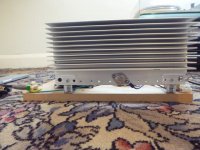
Amazing res. Its only powering one Fe206 Fostex in OB configuration - (I am using an Eminence Delta to run the bottom end, powered by an Accuphase P300) however I am getting more bottom end from the Fostex alone than I ever have before. This amp even sounds better than my restored Pioneer M22 - my previous fave! What a great machine.
I'm about to order a case from China to house 2 channels of the glorious 2SJ28 amplifier. Cant wait...
Has anyone built this amplifier using 2SK180D's? I have two tested ones on the way from Joshvi. I take it that the bias supply will need to be negative with respect to ground - what kind of positive supply voltage would I need? (using the V193 choke design). I take it also that my heatsinking may need to drastically increase from what I am currently using with the 2SJ28 VFETs?
Has anyone built this amplifier using 2SK180D's? I have two tested ones on the way from Joshvi. I take it that the bias supply will need to be negative with respect to ground - what kind of positive supply voltage would I need? (using the V193 choke design). I take it also that my heatsinking may need to drastically increase from what I am currently using with the 2SJ28 VFETs?
Here's a whole video dedicated to a nice loadline for that part. 🙂
https://www.youtube.com/watch?v=-c1DMM06Trs
https://www.youtube.com/watch?v=-c1DMM06Trs
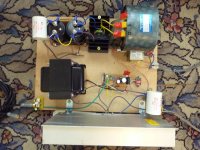
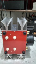
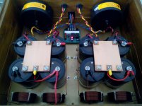
just completed my stereo SIT L'amp self bias, it's the most ambitious of my project since i build the chassis on my own. I'm really satisfied with it's sound, the best part of it is it's huge soundstage compared to my other Papa clone. I keep on smiling for listening to this amplifier, only run it for 1hr. Thanks to MR for the great SIT adventure and OP who give this self bias design (cant remember who posted it)
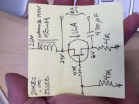
I'm using 2x25V 300VA toroid, with Rk 2x8R paralel caddock resistor resulting 7V bias and 25Vds
one is never enough, but 3 class a should be enough for me 🙂 this will be my last amplifier journey, Luminaria parts is waiting to be completed, will be 2nd preamp after dcb1. next journey will be speaker building
Attachments
-
 IMG_20160820_195700_HDR.jpg445.5 KB · Views: 576
 -
 IMG_20160820_214014_HDR.jpg297.5 KB · Views: 557
 -
 IMG_20160820_214116_HDR_1471704211496.jpg187.1 KB · Views: 544
 -
 IMG_20160820_214403_HDR.jpg898 KB · Views: 552
 -
 IMG_20160820_214439_HDR.jpg836.5 KB · Views: 533
 -
 IMG_20160820_214825_HDR.jpg911.7 KB · Views: 296
Last edited:
Looks good - Are you doing the "pseudo-parafeed" trick of returning the speaker through cap to the source/resistor junction? If so, what value cap are you using? Driving what speakers?
Alot of fun 😀Nice! I'm glad you're having fun. 🙂
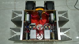
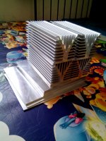
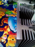
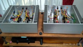
base plate is 5mm, front and rear 3mm, HS is attached on 10mm plate. When I buy the plate, i give extra 5cm from my desired layout. to get a precise cut, I find nearby workshop with giant machine which can cut metal plat up to 6mm, its like a huge 3m scissor. What I need to do is to make a perfect rectangular line to be cut. for 10mm plate, I also find milling workshop which cut nicely. I find cutting tolerance is less than 0.5mm.gadut how work this creative heatsink ?
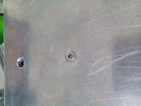
The hardest part is to make a precise drill on the plate and tap each of them, I only have hand drill and hand tap. with alot of practice, all plate can be aligned. if you have drill press will be alot better
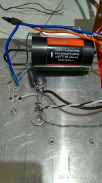
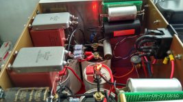
yes I use your schematic, CRC psu with C rifa 33mF - 10x paralel 1R 3W, last C is bypassed by 60uF motor run cap. choke is 300mH 3A 1.8Rdc.Looks good - Are you doing the "pseudo-parafeed" trick of returning the speaker through cap to the source/resistor junction? If so, what value cap are you using? Driving what speakers?
Cout is nichicon super 4.700uf // 30uF mbgo2 // 0.1uF rusia silver mica, which drive Alpair 10p
Beautifull morning, SIT had been running more than 1hr and warm up steady. I set dcb1 to full volume, close the door and 'What a difference a day makes' plays nicely 😀
Attachments
Alot of fun 😀
base plate is 5mm, front and rear 3mm, HS is attached on 10mm plate. When I buy the plate, i give extra 5cm from my desired layout. to get a precise cut, I find nearby workshop with giant machine which can cut metal plat up to 6mm, its like a huge 3m scissor. What I need to do is to make a perfect rectangular line to be cut. for 10mm plate, I also find milling workshop which cut nicely. I find cutting tolerance is less than 0.5mm.
The hardest part is to make a precise drill on the plate and tap each of them, I only have hand drill and hand tap. with alot of practice, all plate can be aligned. if you have drill press will be alot better
yes I use your schematic, CRC psu with C rifa 33mF - 10x paralel 1R 3W, last C is bypassed by 60uF motor run cap. choke is 300mH 3A 1.8Rdc.
Cout is nichicon super 4.700uf // 30uF mbgo2 // 0.1uF rusia silver mica, which drive Alpair 10p
Beautifull morning, SIT had been running more than 1hr and warm up steady. I set dcb1 to full volume, close the door and 'What a difference a day makes' plays nicely 😀
@ Gadut
That is DIY

All hand made ! Cool 🙂
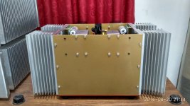
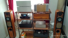
Surprise i never see psu transformer close to speakers outputs...
normaly they are in opposite direction corner far distance from audio signal wirings
...anyway shield steel cover probably work so why not ?
Some builders put big transformer(s) in separate little box connected by shielded power cord to amplifier audio circuits
so all mechanical vibration and magnetic field are gone finaly : two boxes amp with less heavy weight.
I like very much Your build congratulations Gadut
My kindest regards

Looks good - Are you doing the "pseudo-parafeed" trick of returning the speaker through cap to the source/resistor junction? If so, what value cap are you using? Driving what speakers?
any schematic somewhere
 of this pseudo parafeed trick ?
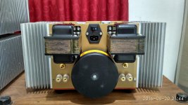
laser temp meter shows hottest part is caddock resistor 49°C, while HS parts not more than 45°Cthanks a lot , working temperature?
well my layout seems break all rules for parts placement and cable routing. When I build the chassis, I did not have any final parts layout yet, just put them slowly once I have all parts. When the plates had been cut, rifa/motor run/rusia caps were not bought yet. My original plan was to use MR original schematic and use my FW general psu connected with PowerCon, just like J2/M2. but then this pseudo parafeed came out. So i took out mauro penasa myref toroid.@ Gadut
That is DIY
All hand made ! Cool 🙂
Surprise i never see psu transformer close to speakers outputs...
normaly they are in opposite direction corner far distance from audio signal wirings
...anyway shield steel cover probably work so why not ?
Some builders put big transformer(s) in separate little box connected by shielded power cord to amplifier audio circuits
so all mechanical vibration and magnetic field are gone finaly : two boxes amp with less heavy weight.
I like very much Your build congratulations Gadut
My kindest regards

that talema toroid is not shielded, input and ouput are close to it, signal and power cables cross each other, like a spider web 😀 but when dcb1 is set to full volume or when dac out connected directly to SIT, I can only hear a very little hum on A10p when my ear touch it, 10cm away I cant hear any hum. That is when no music playing, so I think that I'm blessed with my work, no issue so far on my build
original schematic is hereany schematic somewhere
http://www.diyaudio.com/forums/pass-labs/201655-lamp-simple-sit-amp-236.html#post4622497
Attachments
- Home
- Amplifiers
- Pass Labs
- L'Amp: A simple SIT Amp