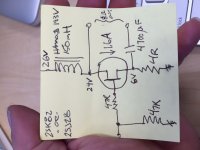
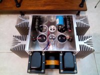
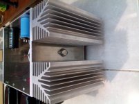
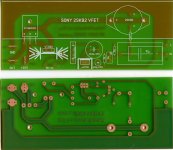
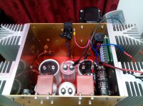
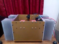
Eventhough Vfet2 is the new hot item, but L'amp is my first love to SIT due to it's simplicity. I'd like to try schematic on post #2355, so I have spent last weekend to do some metal work. Only need to finish the cabling and maybe solid wood faceplate.
My question is : what is the recomended Watt rating for source resistor 4ohm? My calc shows it will dissipate around 9W. I have ordered panasonic 68R 2W, it will be paralel 18pcs to get desired 4ohm 36W, hopefully it will survive
My question is : what is the recomended Watt rating for source resistor 4ohm? My calc shows it will dissipate around 9W. I have ordered panasonic 68R 2W, it will be paralel 18pcs to get desired 4ohm 36W, hopefully it will survive
Attachments
On my breadboard I use two paralleled 12W non inductive wire wounds and they get super hot. For the amp I built for my son, I used a properly heatsinked 50W non inductive wirewound.
36W total rating for 9W dissipation is good in theory, they will survive but will stay at somewhat hot temperature (HOT for human senses but not so for component operation) so probably it don't change the value. Maybe results less *perceptibly* hot than single resistor due to heat spread in various devices......
My question is : what is the recomended Watt rating for source resistor 4ohm? My calc shows it will dissipate around 9W. I have ordered panasonic 68R 2W, it will be paralel 18pcs to get desired 4ohm 36W, hopefully it will survive
Last edited:
23V*2A=46W of dissipation
For a 90W die SIT, we need a generous heatsink to maintain a fair chip temperature, but works (at high side of things). Better linearity at higher dissipation but we can found the thermal limit one day 😉😀🙂
I used with 19V/1.7A
The 2SK18x family is supposed supports far higher due to outrageous max pd
I didn't realized this, thank you. A Japanese site says 2sk82's θj-c is 1 C/W, and if this number is correct, my realistic target should be less than 46W. 😱
I have two boards for a L´Amp with CCS (IXTH6N50D2) permaneder made.
If someone is interested PM me please.
Hi Generg
PM send 🙂
Have a nice week-end
I have two boards for a L´Amp with CCS (IXTH6N50D2) permaneder made.
If someone is interested PM me please.
So, bought those pcb board when I noticed 193V version need 21V AC transformer, not 18v. So my dual 100mH-1ohm chokes could be used for the original inductor version with higher B+?
I have a big 1200VA transformer with 2x18V secondary winding, so I spent some time modeling PSU, here are my findings:

for the original lamp version (but with halogen bulbs), one channel, some ringing at the beginning (up to 55v), is it too bad?

CCS version, no ringing, feeding both channels

for the inductor version (no choke for the PS, the dual 100mH choke will be used for the load), feeding both channels.
I think now I can choose from all the 3 versions, can't I?
Thank you!
Eventhough Vfet2 is the new hot item, but L'amp is my first love to SIT due to it's simplicity. I'd like to try schematic on post #2355, so I have spent last weekend to do some metal work. Only need to finish the cabling and maybe solid wood faceplate.
My question is : what is the recomended Watt rating for source resistor 4ohm? My calc shows it will dissipate around 9W. I have ordered panasonic 68R 2W, it will be paralel 18pcs to get desired 4ohm 36W, hopefully it will survive
Resonably priced Riedon resistor | 50 watts 4R | 1% |
wire wound , non-inductive , aluminium housed ,
easy to atach with biger heat sink if necessairy 🙂
resistors_riedon
So, bought those pcb board when I noticed 193V version need 21V AC transformer, not 18v. So my dual 100mH-1ohm chokes could be used for the original inductor version with higher B+?
I have a big 1200VA transformer with 2x18V secondary winding, so I spent some time modeling PSU, here are my findings:
for the original lamp version (but with halogen bulbs), one channel, some ringing at the beginning (up to 55v), is it too bad?
CCS version, no ringing, feeding both channels
for the inductor version (no choke for the PS, the dual 100mH choke will be used for the load), feeding both channels.
I think now I can choose from all the 3 versions, can't I?
Thank you!
Hello
For the 193V inductor version B+ should be around 24V. This can be obtained with the 18V transformer (series secondaries and choke input)

For the other versions they look ok to me but i think that the filtering is a bit overkill for the CCS version.
Hello
For the 193V inductor version B+ should be around 24V. This can be obtained with the 18V transformer (series secondaries and choke input)
View attachment 546907
For the other versions they look ok to me but i think that the filtering is a bit overkill for the CCS version.
Thank you Jostwid, but I have only one dual choke, so if I want to build the inductor version I have to use it for the load and not for the PSU 🙂
The in ductor is 100mH, 1 ohm, 4A per channel, so I think it's almost the same of two big spool of wire used for L'Amp part deux where B+ was 35v.
Ciao!
PS: Can I use a small 18v transformer for bias psu?
When Michael did the inductor version he used a spool of wire that had quite some resistance (maybe 5 to 7 Ohms?) At almost 2 amps through these inductors the voltage loss was maybe 10 volts, so he needed the B+ of 35.
You can always do an additional inductor for the PS. No need for iron. With 10mH and 1 to 2 Ohms resistance you can get good results in the PS.
Yes you can use a small 18V trafo for the bias supply
Salve
Thank you jostwid, I missed that point!
is there somewhere a SI:tamp schematic with bipolar power supply to get rid of the 10000uf DC output cap ?🙂
Very nice looking amp. if you don't mind me asking, how would you modify your schematic to replace the 2SK28 (using the same power supply) with the following devices:Eventhough Vfet2 is the new hot item, but L'amp is my first love to SIT due to it's simplicity. I'd like to try schematic on post #2355, so I have spent last weekend to do some metal work. Only need to finish the cabling and maybe solid wood faceplate.
My question is : what is the recomended Watt rating for source resistor 4ohm? My calc shows it will dissipate around 9W. I have ordered panasonic 68R 2W, it will be paralel 18pcs to get desired 4ohm 36W, hopefully it will survive
1) 2SJ28,
and
2) 2SK70 (NEC Vfet). Operating characteristics are similar to Sony 2SK82 but not identical.
3) Tokin 2SK180
TIA
I'm using 2SK82, no idea for other type.Very nice looking amp. if you don't mind me asking, how would you modify...
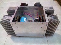
Just power up with sef bias 1ch and it sings lovely, mid and high is special eventhough low bass not as strong as AJ but i'm happy now (my previous result is dull with separate bias). my Alpair10 is being delivered from singapore, SIT + FR seems good couple 🙂
using 25V toroid, I get Vds 29V and 7V bias, a little higher.Rs is veryyy hott,around 105°C which means I should get 4R with huge heatsink.
I only play for 30minutes but Cout is very hot and it's inside oil blown out, really bad,I should have used cheap cap for first try. I think that I put it on wrong direction where + is connected to SITsource and - to speaker - terminal.
Tomorrow wil try again with - to SITsource, I got many nichicon kg 4700uf for testing
Attachments

Last edited:
2SK70
My firsts testings with SIT SE amplifiers was with 2SK70. Basically same use than 2SK82. With adjustable bias one can use same circuit and compare. 2SK70 has a 100W die chip so it calls to be biased with 2SK82 power levels (I used 15 to 22V and 1.5 to 1.8A in my testings). µ e rd is in same ballpark.Very nice looking amp. if you don't mind me asking, how would you modify your schematic to replace the 2SK28 (using the same power supply) with the following devices:
1) 2SJ28,
and
2) 2SK70 (NEC Vfet). Operating characteristics are similar to Sony 2SK82 but not identical.
3) Tokin 2SK180
TIA
My firsts testings with SIT SE amplifiers was with 2SK70. Basically same use than 2SK82. With adjustable bias one can use same circuit and compare. 2SK70 has a 100W die chip so it calls to be biased with 2SK82 power levels (I used 15 to 22V and 1.5 to 1.8A in my testings). µ e rd is in same ballpark.
Thank you very useful info.
I didn't realized this, thank you. A Japanese site says 2sk82's θj-c is 1 C/W, and if this number is correct, my realistic target should be less than 46W. 😱
Plasnu, this is important data. Do you have more data for 2sk82? I need to know:
-Max total power dissipation
-Max junction temperature
Thanks
- Home
- Amplifiers
- Pass Labs
- L'Amp: A simple SIT Amp