Well 6 to 12 6as7a's just using the filiments would look neat and
at the same time make people think you had an otl amp ! And what
about an aluminum engine block as a heatsink !
Would be very nice.
Add a lots of meters, then a real steampunk amp.
Last edited:
The CCS version on my website was a good bit darker. 🙂
HI there amp Builders,
Can some one help me with as simple a CCS as Michael has used in his
CCS Addendum But I have a P channel SIT amp.
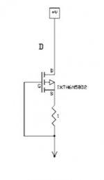
He has a N channel 2SK82 with a IXTH6N50D2 CCS thats a depletion mode MOSFET, But I have a P channel 2sj82 SIT
If you have a super quiet supply, you could just flip it around maybe, but it would be better to make up a p-channel current source.
Since there seem to be a lot of orphaned 2SJ28's out there, maybe I should whip something up when I get back 🙂
Since there seem to be a lot of orphaned 2SJ28's out there, maybe I should whip something up when I get back 🙂
Well, I can imagine no trouble to reversing connections in one 2-terminal CCS (when using depletion CCS, to maintain correct voltage polarity into CCS MOSFET), so if one already choose/prefer the depletion CCS model one can use same depletion MOSFET from N-channel version to P-channel version. Basically same performance from N version with some little difference due to different P channel drain resistance.
I only add this because P-channel depletion MOSFET/JFET is very rare if someone find one actually.
I only add this because P-channel depletion MOSFET/JFET is very rare if someone find one actually.
HI there amp Builders,
Can some one help me with as simple a CCS as Michael has used in his
CCS Addendum But I have a P channel SIT amp.
He has a N channel 2SK82 with a IXTH6N50D2 CCS thats a depletion mode MOSFET, But I have a P channel 2sj82 SIT
point me to exact schematic and I'll flip it for you
point me to exact schematic and I'll flip it for you
Hi Zen Mod, it's on the 4th page of Mike's pdf:
http://www.audiohobby.com/pdf/lamp ccs.pdf
Cheers,
Dennis
Yes, but we'd want to explore the sweet spot specifically with the 180.
Possibly I could answer that on my Blab this weekend. 🙂
Just wanted to add too, I have strong interest in the ccs with 180, as well as with sj28. Perhaps these two could act as a continuation of L'amp and du jour parts.
Hi Zen Mod, it's on the 4th page of Mike's pdf:
http://www.audiohobby.com/pdf/lamp ccs.pdf
Cheers,
Dennis
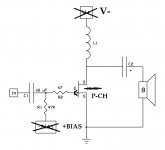
something like this
of course , to make it more silent , it's always possible to inject some of PSU ripple in input gate , but I'm lazy to calc that
roughly - resistor which value is 10K multiplied with amp's gain
Attachments

Last edited:
Well, the builder can experiment with both proposals, if desired and if have spare time. So the builder can decide the sound flavor with own ears 🙂. (remember to check the cap polarity). Of course if don't have some constructional penalty.
(and, by the way, personally I also have a motive to move the speaker leg; the audio current path becomes shorter, and CCS shields the output from PSU noise, but is only my preferences)
(and, by the way, personally I also have a motive to move the speaker leg; the audio current path becomes shorter, and CCS shields the output from PSU noise, but is only my preferences)
All,
This is my first post on this thread, but I've been playing with various single ended configurations of the SIT amp, mostly using the readily available 2SJ28 P-Channel parts. I have tried what Michael mentions, flipping the IXTH6N50D2 CCS on its head. In this config, the gate of the IXTH6N50D2 is tied to the negative rail, the 1R connects the source to the negative rail and the drains of the IXTH6N50D2 and 2SJ28 meet.
Using a test switching power supply, noise was more evident than other versions of this amp circuit. But, using a very quiet CLC filtered power supply with 22,000uF-6mH choke-22,000uF, noise was not an issue.
I am a fan of auto-bias on single ended amps though, and biasing up this double-headed monster with source resistors top and bottom is tricky business indeed. For most 2SJ28 parts I have tried, I have found it easier to hit the right Vds and Vgs on the 2SJ28 with a 0.75 or so Ohm source resistance (rather than 1R) on the IXTH6N50D2. But it's a balancing act for sure.
I'll post soon about some interesting bypassing techniques I have been playing with for these amplifier designs.
Greg
All,
I have been getting putstanding results with an unusual configuration of the L'amp SIT amplifer.
For background, I am a traditional tube amp junkie. I have been building amps for about 15 years, simple single ended and push-pull designs, but mostly single ended. While my best push-pull amps use transformer coupling and phase-splitting with fixed bias, I have a preference in single-ended topologies for autobias, rather than fixed. I use full range drivers for speakers. I am, however a solid-state novice, newbie and idiot.
The first version of the L'amp I tried was the inductor form, using the Hammond 193V. I was extremely impressed with the sound and started playing with variations in this configuration. I drew several variants, doing the math for the impedance of the inductor, tried different biasing schemes, etc. Like I said, I prefer autobias in my single ended tube amps, but was frustrated with the SIT requirements of an absolutely enormous bypass capacitor for a source resistor in conjunction with the very large coupling capacitor. I also really wanted to avoid the greatly complicated power supply required for fixed bias.
At some point - and I'm sure this is old hat for many of you - I realized all of these L'amp circuits would be characterized in the tube domain as parafeed. The lamps, inductor or CCS load the device but instead of the primary coil of an output transformer being parallel with the SIT, the voice coil of a single driver speaker is! Once I realized that, I remembered that there are numerous options with regard to the placement of bypass and coupling (parafeed) caps.
If you take a look at Lynn Olson's outstanding presentation on "Current Loops" from the 2004 European Triode Festival at ETF Presentation there are comparative illustrations of various topologies. Other excellent resources are Paul Joppa's "Twelve Ways to Parafeed" from Volume 6, Number 5 of Valve Magazine, and Lynn Olson's "Periodic Table" article from Issue 16 of Vacuum Tube Valley.
Ignoring the push-pull possibilites for now, take a look at the Parafeed topology that Lynn identifies as "Western Electric (output)" in the ETF article. In other writings this is referred to as the "Western Electric Connection" or "Western Electric Parafeed".
To try this with the L'amp, imagine the source resistor (Figure 11) version of the original L'amp article, but with the Hammond 193V instead of the lamps. Or remove the bias supply and add a source resistor to the L'amp 193V version. Now you remove the cap from drain-speaker connection. You then return the speaker to the source-bias resistor connection instead of ground through the cap. For the 2SK82/2SJ28 it looks like this:

By using the WE Connection, the need for a separate source resistor bypass cap is eliminated. Using Paul Joppa's rule of thumb for sizing the parafeed cap (2L/R^2) you get 4,687.5 uF for the Hammond 193V with an 8 ohm speaker. I have used anywhere from 4000 to 4700uF for this cap. You'll find that adjusting this cap value seasons the sound of the mid-low bass. Find the brand of the cap (or film bypass combination) that gives you the rendering of the highs you like and adjust the value for the depth of bass that you like.
If you read deeply about this style of parafeed on the web, you'll see there are possibilities for noise or positive feedback using this conection but I don't hear them, and I don't have the capability to measure for them.
I encourage anyone this amp on a breadboard to try this bypassing scheme. Yes, you need a few more volts out of the B+ power supply, but there is no need for the second bias supply. I have used the amp in this configuration with a few different full-range single drivers, and with a simple cross-over with a twelve inch driver and hornloaded tweeter with great results. I tried a conventional commercial speaker - a Monitor Audio two-way - and got less spectacular performance. I don't know if it was the complicated crossover or the lower effiency of these speakers but it was not great.
It's exciting to be able to try out these alternative topologies and ancient techniques using the relatively inexpensive SITs and associated components. In the tube domain, each experiment seems to need its own tubes, output transformers, sockets, power supply requirements, etc... In just a few months with these parts I've been able to try things I have always put on the backburner with tube amps...
G
I have been getting putstanding results with an unusual configuration of the L'amp SIT amplifer.
For background, I am a traditional tube amp junkie. I have been building amps for about 15 years, simple single ended and push-pull designs, but mostly single ended. While my best push-pull amps use transformer coupling and phase-splitting with fixed bias, I have a preference in single-ended topologies for autobias, rather than fixed. I use full range drivers for speakers. I am, however a solid-state novice, newbie and idiot.
The first version of the L'amp I tried was the inductor form, using the Hammond 193V. I was extremely impressed with the sound and started playing with variations in this configuration. I drew several variants, doing the math for the impedance of the inductor, tried different biasing schemes, etc. Like I said, I prefer autobias in my single ended tube amps, but was frustrated with the SIT requirements of an absolutely enormous bypass capacitor for a source resistor in conjunction with the very large coupling capacitor. I also really wanted to avoid the greatly complicated power supply required for fixed bias.
At some point - and I'm sure this is old hat for many of you - I realized all of these L'amp circuits would be characterized in the tube domain as parafeed. The lamps, inductor or CCS load the device but instead of the primary coil of an output transformer being parallel with the SIT, the voice coil of a single driver speaker is! Once I realized that, I remembered that there are numerous options with regard to the placement of bypass and coupling (parafeed) caps.
If you take a look at Lynn Olson's outstanding presentation on "Current Loops" from the 2004 European Triode Festival at ETF Presentation there are comparative illustrations of various topologies. Other excellent resources are Paul Joppa's "Twelve Ways to Parafeed" from Volume 6, Number 5 of Valve Magazine, and Lynn Olson's "Periodic Table" article from Issue 16 of Vacuum Tube Valley.
Ignoring the push-pull possibilites for now, take a look at the Parafeed topology that Lynn identifies as "Western Electric (output)" in the ETF article. In other writings this is referred to as the "Western Electric Connection" or "Western Electric Parafeed".
To try this with the L'amp, imagine the source resistor (Figure 11) version of the original L'amp article, but with the Hammond 193V instead of the lamps. Or remove the bias supply and add a source resistor to the L'amp 193V version. Now you remove the cap from drain-speaker connection. You then return the speaker to the source-bias resistor connection instead of ground through the cap. For the 2SK82/2SJ28 it looks like this:
By using the WE Connection, the need for a separate source resistor bypass cap is eliminated. Using Paul Joppa's rule of thumb for sizing the parafeed cap (2L/R^2) you get 4,687.5 uF for the Hammond 193V with an 8 ohm speaker. I have used anywhere from 4000 to 4700uF for this cap. You'll find that adjusting this cap value seasons the sound of the mid-low bass. Find the brand of the cap (or film bypass combination) that gives you the rendering of the highs you like and adjust the value for the depth of bass that you like.
If you read deeply about this style of parafeed on the web, you'll see there are possibilities for noise or positive feedback using this conection but I don't hear them, and I don't have the capability to measure for them.
I encourage anyone this amp on a breadboard to try this bypassing scheme. Yes, you need a few more volts out of the B+ power supply, but there is no need for the second bias supply. I have used the amp in this configuration with a few different full-range single drivers, and with a simple cross-over with a twelve inch driver and hornloaded tweeter with great results. I tried a conventional commercial speaker - a Monitor Audio two-way - and got less spectacular performance. I don't know if it was the complicated crossover or the lower effiency of these speakers but it was not great.
It's exciting to be able to try out these alternative topologies and ancient techniques using the relatively inexpensive SITs and associated components. In the tube domain, each experiment seems to need its own tubes, output transformers, sockets, power supply requirements, etc... In just a few months with these parts I've been able to try things I have always put on the backburner with tube amps...
G
Pa is using something similar , practically the same , in his SIT 1
yup , WE connection , from time when iron was cheaper than uF
yup , WE connection , from time when iron was cheaper than uF
Hi GregChristieAll,
I have been getting putstanding results with an unusual configuration of the L'amp SIT amplifer.
For background, I am a traditional tube amp junkie. I have been building amps for about 15 years, simple single ended and push-pull designs, but mostly single ended....Parafeed topology that Lynn identifies as "Western Electric (output)" in the ETF article. In other writings this is referred to as the "Western Electric Connection" or "Western Electric Parafeed".
For the 2SK82/2SJ28 it looks like this:
View attachment 532190
I encourage anyone this amp on a breadboard to try this bypassing scheme. Yes, you need a few more volts out of the B+ power supply, but there is no need for the second bias supply. I have used the amp in this configuration with a few different full-range single drivers, and with a simple cross-over with a twelve inch driver and hornloaded tweeter with great results. I tried a conventional commercial speaker - a Monitor Audio two-way - and got less spectacular performance. I don't know if it was the complicated crossover or the lower effiency of these speakers but it was not great.
It's exciting to be able to try out these alternative topologies and ancient techniques using the relatively inexpensive SITs and associated components. In the tube domain, each experiment seems to need its own tubes, output transformers, sockets, power supply requirements, etc... In just a few months with these parts I've been able to try things I have always put on the backburner with tube amps...
G
Thanks for your interestig post's no doubt all single-ended topologys was not explored.
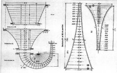
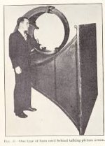
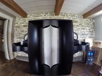
Always nostalgic of Western-Electric era specialy horn's and first triode amplifiers used width cinema shows.
Mr Pass write us about his upcoming 2SJ28 single diy amplifier schematic but he is probably very busy
with new F7 amp production so pattience is a key to find one more treasure

One option is to make a single-ended SIT amplifier using a P channel follower
and biased by a constant current source.
Very easy to do.
I certainly can deliver that and so you guys should consider buying those up.
That said, I would still like to see some of these PP circuits built.
And here's the good news....On my end this will proceed over the next few weeks.
Those with only one polarity of VFETs will be addressed in a separate design after that.
😎
Kind regards
Attachments
-
 4A459E50-5D04-4DA3-8A52-56E084053FE3.JPG146.8 KB · Views: 941
 -
 A4B63936-0DEE-4D4E-8A9F-A14BB75EBC17.JPG110.9 KB · Views: 997
 -
 DA64E411-BF9C-4002-84B4-F2FBF34B89F6.JPG17.7 KB · Views: 904
 -
 6AA37C79-A313-4DBD-ABD6-372EF90953A3.JPG387.2 KB · Views: 898
 -
 D958D8DD-0824-45A4-B881-DE94BE71DA54.JPG625.3 KB · Views: 228
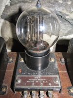
Does anyone have a source for SITs at this point?
Yes try buy in this shop all Sony are genuine:
2SJ28 P Channel VFET From Sony
I like these "parafeed"/current loops style; very smart and elegant!All,
I have been getting putstanding results with an unusual configuration of the L'amp SIT amplifer.
For background, I am a traditional tube amp junkie. I have been building amps for about 15 years, simple single ended and push-pull designs, but mostly single ended. While my best push-pull amps use transformer coupling and phase-splitting with fixed bias, I have a preference in single-ended topologies for autobias, rather than fixed. I use full range drivers for speakers. I am, however a solid-state novice, newbie and idiot.
The first version of the L'amp I tried was the inductor form, using the Hammond 193V. I was extremely impressed with the sound and started playing with variations in this configuration. I drew several variants, doing the math for the impedance of the inductor, tried different biasing schemes, etc. Like I said, I prefer autobias in my single ended tube amps, but was frustrated with the SIT requirements of an absolutely enormous bypass capacitor for a source resistor in conjunction with the very large coupling capacitor. I also really wanted to avoid the greatly complicated power supply required for fixed bias.
At some point - and I'm sure this is old hat for many of you - I realized all of these L'amp circuits would be characterized in the tube domain as parafeed. The lamps, inductor or CCS load the device but instead of the primary coil of an output transformer being parallel with the SIT, the voice coil of a single driver speaker is! Once I realized that, I remembered that there are numerous options with regard to the placement of bypass and coupling (parafeed) caps.
If you take a look at Lynn Olson's outstanding presentation on "Current Loops" from the 2004 European Triode Festival at ETF Presentation there are comparative illustrations of various topologies. Other excellent resources are Paul Joppa's "Twelve Ways to Parafeed" from Volume 6, Number 5 of Valve Magazine, and Lynn Olson's "Periodic Table" article from Issue 16 of Vacuum Tube Valley.
Ignoring the push-pull possibilites for now, take a look at the Parafeed topology that Lynn identifies as "Western Electric (output)" in the ETF article. In other writings this is referred to as the "Western Electric Connection" or "Western Electric Parafeed".
To try this with the L'amp, imagine the source resistor (Figure 11) version of the original L'amp article, but with the Hammond 193V instead of the lamps. Or remove the bias supply and add a source resistor to the L'amp 193V version. Now you remove the cap from drain-speaker connection. You then return the speaker to the source-bias resistor connection instead of ground through the cap. For the 2SK82/2SJ28 it looks like this:
View attachment 532190
By using the WE Connection, the need for a separate source resistor bypass cap is eliminated. Using Paul Joppa's rule of thumb for sizing the parafeed cap (2L/R^2) you get 4,687.5 uF for the Hammond 193V with an 8 ohm speaker. I have used anywhere from 4000 to 4700uF for this cap. You'll find that adjusting this cap value seasons the sound of the mid-low bass. Find the brand of the cap (or film bypass combination) that gives you the rendering of the highs you like and adjust the value for the depth of bass that you like.
If you read deeply about this style of parafeed on the web, you'll see there are possibilities for noise or positive feedback using this conection but I don't hear them, and I don't have the capability to measure for them.
I encourage anyone this amp on a breadboard to try this bypassing scheme. Yes, you need a few more volts out of the B+ power supply, but there is no need for the second bias supply. I have used the amp in this configuration with a few different full-range single drivers, and with a simple cross-over with a twelve inch driver and hornloaded tweeter with great results. I tried a conventional commercial speaker - a Monitor Audio two-way - and got less spectacular performance. I don't know if it was the complicated crossover or the lower effiency of these speakers but it was not great.
It's exciting to be able to try out these alternative topologies and ancient techniques using the relatively inexpensive SITs and associated components. In the tube domain, each experiment seems to need its own tubes, output transformers, sockets, power supply requirements, etc... In just a few months with these parts I've been able to try things I have always put on the backburner with tube amps...
G
- Home
- Amplifiers
- Pass Labs
- L'Amp: A simple SIT Amp