I'll use my little UA-25EX to generate 44.1 SPDIF and see what I can learn.
...what I learned was that when no rate is specified, SoX defaults to 48k, which just happened to be the input frequency of my SPDIF appliances. In order to play 44.1k material, '-r 44100' must be in the front-end of the SoX command line (the SoX pipe 'acceptor' adapts automatically, as evidenced by proc/asound/Botic/pcm0p/sub0/hw_params).
Certainly, an embedded sensor for input sample rate would be a direct and universal approach to adapting the RPi software sample rate parameters. ...and perhaps it's worth looking into ALSA's own SPDIF output. It might add some USB bandwidth or otherwise influence performance. From the the 'aplay -L' list:
Code:
    iec958:CARD=miniStreamer,DEV=0
    miniStreamer, USB Audio
IEC958 (S/PDIF) Digital Audio OutputThat's a good thought, but I believe your "ALSA SPDIF" is just the interface to a physical spdif output (on your mother board perhaps). You would still need to set the rate for that device, or live with the default rate that is defined in the global alsa configuration file. Unfortunately it doesn't "add bandwidth" or "otherwise influence performance". It's just another ALSA output device....what I learned was that when no rate is specified, SoX defaults to 48k, which just happened to be the input frequency of my SPDIF appliances. In order to play 44.1k material, '-r 44100' must be in the front-end of the SoX command line (the SoX pipe 'acceptor' adapts automatically, as evidenced by proc/asound/Botic/pcm0p/sub0/hw_params).
Certainly, an embedded sensor for input sample rate would be a direct and universal approach to adapting the RPi software sample rate parameters. ...and perhaps it's worth looking into ALSA's own SPDIF output. It might add some USB bandwidth or otherwise influence performance. From the the 'aplay -L' list:Code:iec958:CARD=miniStreamer,DEV=0 miniStreamer, USB Audio IEC958 (S/PDIF) Digital Audio Output
As far as an "embedded sensor", if you mean one that can discover the rate of raw audio that is already inside the ALSA system I don't know of a solution for that. You need something that can get the rate of the audio stream before it becomes raw (ALSA) PCM audio. In my case I (think I can) access a pin on the USB spdif dongle that will let me figure out the rate because the pin contains the word clock signal of the spdif, which it the same frequency as the sample rate. But I still won't know the bit depth! I may have to live with truncating everything to 16 bits and then adding dither. That's totally fine in my book, and its the only way to simultaneously have 96k audio in and out running across a USB-high-speed bus!
I learned a new thing about ecasound buffering while testing the spdif interface. It seems that if I simply use the "-b" option to specify the buffer size it is always overridden by a default value (which was 256 samples). I figured this out only after printing the highest level of debug info using the "-ddd" option, in response to experiencing ALSA overruns about every 10 minutes or so. But if I use the combination of buffer related options of both "-B" and "-b" I can set the buffer size to whatever I desire. I ended up using "-B:rt -b:1024" to eliminate the overruns.
Hopefully this will be useful for someone out there...
Hopefully this will be useful for someone out there...
Charlie,
I'm working at the moment with your Ladspa filters library, and I have something strange. When I implement an HighShelf using ecasound... -el:ACDf,25,1,8,10071,0.7,6354,0.7 I get something different from what I get in the ACD excel sheet with the same parameters:
- in the excel sheet the difference between the two levels is 8dB as expected,
- but the plugin execution seems to give me a difference between the two levels nearer from10dB (so 2dB difference).
Could I have made something wrong? Specific data to provide to ease the analysis if relevant?
I'm surprised as the LowShelf -el:ACDf,25,1,0,631,0.5,1585,0.5 provided me better consistency.
best regards,
JMF
Using my current setup I made some measurements of the ACDf type 25 filter that you mention above, called from ecasound.
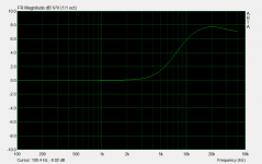
The first attachment shows the type 25 shelving filter with Fp=10071, Qp=0.7, Fz=6354, Qz=0.7. I actually get slightly less than the 8dB of gain that this filter should provide but I believe that one of the anti-aliasing filters is already starting to roll off the response up at 20kHz.
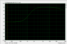
The second attachment is the same amount of boost, but with Fp=1kHz. You can see you get 8dB of boost with this filter - exactly what is expected. You can also see the high end roll off (e.g. about -0.75dB at 20kHz) more clearly in this plot.
I do not know why you would be seeing MORE gain from the filter at high frequencies. I do not observe that behavior on my system.
Attachments
Hello,
Please find attached the response file (Holmimpulse). In thge response, in green, the miniDSP one measured through the soundcard.
The ecp file contains:
tweeter = -eadb:-10 \
-el:ACDf,25,1,8,10071,0.7,6354,0.7
The ACD one is in blue and elaborated by sending the ecasound output to a file, and analysing the resulting file directly.
This is also strange to me as the dBs for lowshelf, and PEQ are normally OK
JMF
Attachments

Last edited:
Did you eliminate all the other filters when you generated the ecasound data? You don't even need to use -eadb... just set the input level lower.Hello,
Please find attached the response file (Holmimpulse). In thge response, in green, the miniDSP one measured through the soundcard.
The ecp file contains:
tweeter = -eadb:-10 \
-el:ACDf,25,1,8,10071,0.7,6354,0.7
The ACD one is in blue and elaborated by sending the ecasound output to a file, and analysing the resulting file directly.
This is also strange to me as the dBs for lowshelf, and PEQ are normally OK
JMF
Please try a couple of different tests:
1. change the filter Fp and Fq, setting Fp equal to 1kHz and Fz to 1585Hz (equal to 1000*10071/6354). Does the filter give 10dB of boost or 8dB?
2. Just remove the type 25 filter completely and then take a measurement. Does the response rise by 2dB at 20kHz or is it flat?
Honestly I do not see anything like this on my systems, so I am very suspicious of your measurement.
Also, what sample rate are you using for the ecasound processing?
Unfortunately it doesn't "add bandwidth" or "otherwise influence performance". It's just another ALSA output device.
My thought was: If ALSA puts out working SPDIF, then the miniStreamer could be an input-only device. With GPIO output, maybe you could get duplex operation up to 96/24. But other priorities for now regardless.
Meanwhile, nothing in the Botic kernel to sense external frequencies - it needs to know in advance. Sorry. 🙁
I don't get it... why would this need to be in the OS kernel?
No need to be in the kernel. But since the Botic kernel is frequency-aware, if a sensor mechanism was already available, then 'Yay!' ...just looking for shortcuts...I don't get it... why would this need to be in the OS kernel?
Hello,
Yes, there may be something wrong with my measurement process, which is however simple. All other filters are disabled, in fact I only manipulate files and don't go to anything physical.
I generate different output files from the same measurement file using the command:
ecasound -b:100 -i:MeasurementSignal.wav -pf:ACDfTweak.ecp -o:ACDfHighShelf_1000_0dB_01.wav
The different filters and associated outputs are (I kepdt the dB parameter at 0 to simplify):
tweeter = -el:ACDf,25,1,0,10071,0.7,6354,0.7
=> ACDfHighShelf_8000_0dB_01.wav
tweeter = -el:ACDf,0,1,0,10071,0.7,6354,0.7
=>ACDfHighShelf_FilterTo0.wav
tweeter = -el:ACDf,25,1,0,1585,0.7,1000,0.7
=>ACDfHighShelf_1000_0dB_01.wav
Then I import the resulting files in HolmImpulse, and I get the attached results:
- 8dB boost for the low frequency one,
- straight for the no filter measurement
- 10 dB boost for the higher frequency one :-(
Samplig rate is 44100
JMF
Attachments
When I compare the plot in your post immediately above (post #390) and the one you posted yesterday (post#385) in this thread, they are slightly different at 20kHz (by 0.5dB). Interesting...
OK, please try one other test:
Move the filter frequencies a bit higher but keeping that same 1.585 times difference in frequency. Does the gain/loss at 20kHz versus DC get even higher?
What MIGHT be happening is that you are running into an effect that happens when a filter has some effect above 5kHz - 10kHz. With an IIR DSP, certain boundary conditions are assumed at Nyquist (0.5* sampling frequency) and DC and sampling frequency. Certain symmetries. The filter shape can be changed as the representation in the z^-1 domain nears the Nyquist frequency. This can cause deviations, but in the past I have only seen these above 5kHz, not for all frequencies like in this case. But it could be the same thing.
For instance I developed a "biquad optimizer" that can be used to eliminate this effect. See the thread here for discussion and examples:
http://www.diyaudio.com/forums/digital-line-level/257313-biquad-optimizer-iir-digital-filters.html
The second plot in the first post of that thread is sort of similar to the filter you are trying to implement.
It could be something else entirely, but let's do some more testing to check...
Edit: another test you can try is to use 96kHz sampling rate with the filter to see if this fixed the problem.
Last edited:
Dear Charlie,
Thanks a lot for your support. About the first plots yesterday, I may have played with the offset to align them. I'll perform the tests that you propose tomorrow evening (starts to be late for me here). I'm sad not to be able to follow your maths explanations... Would nee to go back to school 🙂
JMF
Thanks a lot for your support. About the first plots yesterday, I may have played with the offset to align them. I'll perform the tests that you propose tomorrow evening (starts to be late for me here). I'm sad not to be able to follow your maths explanations... Would nee to go back to school 🙂
JMF
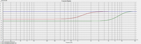
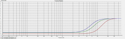
Here are the tests with higher frequencies. The higher the frequency, the bigger the boost.
See attachment.
Filters are generated with:
tweeter = -el:ACDf,25,1,0,7925,0.7,5000,0.7
=>ACDfHighShelf_5000_0dB_01.wav
tweeter = -el:ACDf,25,1,0,15850,0.7,10000,0.7
=>ACDfHighShelf_10000_0dB_01.wav
ecasound -b:100 -i:MeasurementSignal.wav -pf:ACDfTweak.ecp -o:ACDfHighShelf_10000_0dB_01.wav
See attachment.
Filters are generated with:
tweeter = -el:ACDf,25,1,0,7925,0.7,5000,0.7
=>ACDfHighShelf_5000_0dB_01.wav
tweeter = -el:ACDf,25,1,0,15850,0.7,10000,0.7
=>ACDfHighShelf_10000_0dB_01.wav
ecasound -b:100 -i:MeasurementSignal.wav -pf:ACDfTweak.ecp -o:ACDfHighShelf_10000_0dB_01.wav
Attachments
And then tests at 96k: much better ! I'm not able to understand the conclusions, but it seems that your tests pointed out the issue. At 96k, we have the same style of behaviour, but much less pronouced.
I think that there is not the same thing with the miniDSP highshelf filters and the RThighshelf one.
JMF
I think that there is not the same thing with the miniDSP highshelf filters and the RThighshelf one.
JMF
Attachments
You are seeing the effects of the bilinear transform and the fact that the filter is approaching the Nyquist frequency. When you change the rate to 96kHz you are farther away from the Nyquist frequency so the effects are smaller.
When I use ACD-L (the LADSPA version) I can see these effects as well. To do that, just set the "stop frequency for driver response" (cell B10 on the DriverInfo and SystemInfo tab) to something like 50kz and you will see frequencies above the Nyquist frequency (half the sampling frequency) as well as the audio band. Make sure to set the sampling rate there as well (cell B11).
I suggest that you simply adjust the frequencies until you get the 8dB change that you desire and then use those modified values when you implement the filter.
Let me know if you run into any other issues or have trouble getting the filter do to what you want.
Thanks a lot Charlie for the additional explanations, and the way forward.
But does this means that my filters may have different behavior depending on the sampling rate of the music file I play ? 44.1k files having some overall frequency response different from 96k files (at least at higher frequencies, 2dB in my case)?
Best regards,
JM
But does this means that my filters may have different behavior depending on the sampling rate of the music file I play ? 44.1k files having some overall frequency response different from 96k files (at least at higher frequencies, 2dB in my case)?
Best regards,
JM
Thanks a lot Charlie for the additional explanations, and the way forward.
But does this means that my filters may have different behavior depending on the sampling rate of the music file I play ? 44.1k files having some overall frequency response different from 96k files (at least at higher frequencies, 2dB in my case)?
Best regards,
JM
If you use the same filter, then yes. With miniDSP the sample rate is always the same inside the hardware, and so you can correct the filters.
There is a probably a way to eliminate this kind of behavior, but I don't currently know of it. I will check into this to see if I can do something about it.
Last edited:
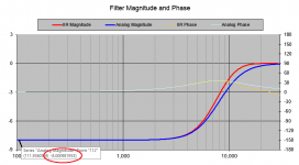
UPDATE:
I have identified a different calculation method for the IIR filter transfer coefficients that should improve the situation. I stumbled on these only after I had already developed all the ACD spreadsheets and ACDf code and then I kind of forgot about it, not thinking there was a need for a total re-write. Honestly, until now I had not seen a problem with the filter response anywhere near as bad as this example, so I didn't make the effort to try and implement this new method. It will definitely take me a few solid days of coding and testing.
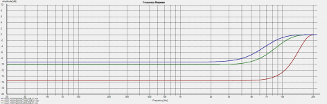
Thanks (JMF11) for bringing this to my attention. The filter response with the new calculation method will give you the red line in the attached plot. There is still some deviation around 10kHz but this is not possible to eliminate because it is due to the Nyquist frequency being so close. But as you can see by the area in the red circle at the bottom left, the attenuation will be correct no matter which frequencies are used in the filter, or the sampling frequency.
I have identified a different calculation method for the IIR filter transfer coefficients that should improve the situation. I stumbled on these only after I had already developed all the ACD spreadsheets and ACDf code and then I kind of forgot about it, not thinking there was a need for a total re-write. Honestly, until now I had not seen a problem with the filter response anywhere near as bad as this example, so I didn't make the effort to try and implement this new method. It will definitely take me a few solid days of coding and testing.
Thanks (JMF11) for bringing this to my attention. The filter response with the new calculation method will give you the red line in the attached plot. There is still some deviation around 10kHz but this is not possible to eliminate because it is due to the Nyquist frequency being so close. But as you can see by the area in the red circle at the bottom left, the attenuation will be correct no matter which frequencies are used in the filter, or the sampling frequency.
Attachments
Last edited:
I've managed to do quite a bit of coding today to implement the changeover of the ACDf LADSPA plugins to the new calculation method. I made much more progress that I had anticipated and was able to get all the filter types re-coded and tested. It's looking good at this time. I will do some more sanity checking tomorrow since my brain is a bit fried after going at it for 10 hours...
Since I was re-writing things anyway I have decided to change the format of the LOW_SHELF and HIGH_SHELF to match the miniDSP input parameter style where the frequency supplied by the user becomes the "center" of the shelf and the gain controls how wide in frequency the shelf will be. I also made it possible to set the Q to match the miniDSP interface. Most people don't realize that ACDf also has a first order shelf filter, which I have not seen for miniDSP. The first order shelf is very useful for loudspeakers (e.g. for baffle step compensation) and can't really be created with miniDSP's second order shelving filters.
I did some thinking about the Active Crossover Design Tools. There is currently a separate set of tools for LADSPA (e.g. ACDf) and for the miniDSP (the "original" ACD). I would like to combine both of these into one tool, and will probably drop the "analog" part of the tools since I'm really not aware of anyone using ACD for design of analog crossovers (who is doing that these days?). Anyway, the proposed next ACD release (let's call it 'ACD-LM' for ACD for LADSPA and miniDSP) would be interesting because people will have a better match for the miniDSP filter set and they could move an existing design over to a LADSPA system at a later time without having to change anything.
From time to time I receive positive feedback now and them from people who have used ACD to design their loudspeaker crossovers. I'm glad that there is a community of users out there enjoying what I originally created for my own loudspeaker crossover design needs. If anyone has an idea for changes or upgrades that might improve the tools, now is a good time to contact me about it.
I finally got around to giving this a try (getting the sample rate from the I2S LFCLK pin of the miniStreamer). There is good news and bad news...Speaking of the sample rate... You simple need to differentiate between all possible rates. In this case the max rate that can be accommodated is 96kHz, and below there is only 88.2k, 48k and 44.1k for audio. So you need only to be able to differentiate these.
It turns out that the pigpio library (now included with the Raspbian OS distro) includes a couple of short C programs that do frequency counting as examples of what the library can do. These could be used directly on this problem along with an output from the miniStreamer hardware. The miniStreamer manual shows that the word clock (LRCLOCK) for the I2S version of the spdif input (when miniStreamer is the master clock) is made available on a header pin. The word clock is the same as the sample rate, which is helpful because if we needed to look at the bit clock of the spdif signal itself we would need to measure frequencies up to 6MHz or so. Measuring 96kHz is a much easier task. By connecting the word clock to a free GPIO pin of the Pi and using the pigpio frequency counter program the frequency is updated at the command prompt every N 10ths of a second. This could be incorporated into a shell script that kills and restarts ecasound or sox when the spdif rate (and thus the frequency) changes. This approach would be equivalent to ALSA stopping and restarting a LADSPA plugin automatically when the sample rate changes.
GOOD NEWS:
So, the hardware connections were very simple. Two wires between Raspberry Pi and the streamer (GND connecting GND, and the LRCLK connected to GPIO4) was all it took. Then I installed the pigpio library using apt-get and compiled the program "Frequency Counter 2" that I downloaded from the pigpio web page. When I ran the program I immediately got a stream of the frequency reported at the console. It took 1-2 sec (might have been faster but that was the reporting rate) before the rate was accurately reporting 96kHz, more or less. I collected data for a time and then ran statistics on it using LibreOffice Calc (included with Raspbian). Here is the result:
Code:
[FONT="Courier New"]Mean                      96011.0148367953
Standard Error       3.4234716236
Mode                      96028
Median                   96010
Variance                 3949.6932315953
Standard Dev         62.8465848841
Kurtosis                  12.433613503
Skewness               1.2143855816
Range                     811
Minimum                95700
Maximum               96511[/FONT]
This is pretty darn good! I can easily distinguish one sample rate from another. Also, the CPU usage for this was only FOUR PERCENT!
THE BAD NEWS:
Once I could read the frequency reported at the I2S LRCLK pin I tried to change it from the source. I could not get the reported rate to change. Finally I tried it from the ecasound command that I run on the Pi. Sure enough, THAT is controlling the rate and NOT the incoming spdif signal itself! How on earth is an application supposed to know what spdif rate is coming along on the wire???
BUT THERE IS A SOLUTION
Although it would have been very convenient to get the rate from the miniStreamer, we can't, so we simply need to find some other device that can receive an SPDIF signal, decode it to I2S, and then look at the LRCLK output. So we need a general SPDIF RX chip/circuit, or something like that. Another possibility is to use the spdif bitstream itself and using logic chips spit out some frequency (e.g. 1/64th or 1/192nd of the bit rate) that can be sampled via GPIO.
No matter how it's done, as long as we can get a frequency that is proportional to the bit rate or word clock we can measure it and discriminate out spdif sample rates. The advantage of an spdif RX chip would be that some also make the bit depth available as output. I will have to look around at what RX hardware is available with this capability.
Anyway, it would make for a nice project. Once the sample rate (and possibly the bit depth) are known, the internal audio processing can be reset on changes and the music can keep flowing along...
Last edited:
- Home
- Source & Line
- PC Based
- LADSPA plugin programming for Linux audio crossovers