Raspi2 update
I switched to MoodeAudio to give it a try. I successfully updated the mpd.conf to include the ecasound surround51 command I previously posted. I put in the necessary crossover files in Ladspa and Richard Taylors filters in too. However, the result is the same. MoodeAudio works but only in stereo.
The mpd in Moode has been pipe-enabled per the builder. So, hmmmm.........
So do you get it to pipe the sound to ecasound at all? If not, check if mpd was compiled with pipe out. Make sure you restart the service or reboot completely get any changes to mpd.conf take.
I switched to MoodeAudio to give it a try. I successfully updated the mpd.conf to include the ecasound surround51 command I previously posted. I put in the necessary crossover files in Ladspa and Richard Taylors filters in too. However, the result is the same. MoodeAudio works but only in stereo.
The mpd in Moode has been pipe-enabled per the builder. So, hmmmm.........
Have ubuntu mate installed.
Hi, trying to get Jack server running on pi. It says inactive. Any ideas?
Please
Hi, trying to get Jack server running on pi. It says inactive. Any ideas?
Please
Jack on pi2
Hello
I get
Could not connect to JACK server as client.
-Overall operation failed
-server communication error.
Please check the messages window for more info.
Hello
I get
Could not connect to JACK server as client.
-Overall operation failed
-server communication error.
Please check the messages window for more info.
Success! With Odroid C1+
Hello,
Thanks to some timely tips from Odal3 and taking the time to compile MPD from scratch I have successfully implemented a LADSPA three-way crossover using an external USB card that can do surround sound. I am getting six channels out that are individually crossed over. The whole thing is tri-amped to open-baffle speakers. I will do further testing but it sounds great now.
To share how this happened what are the suggestions as what format? I can write up a little white paper?
Thanks,
James
Jmccanna - Nice job!
@Charlie - If you are OK with it, I would recommend to keep some up to date instructions on how to set it all up on the audio.claub.net website. Kind of like a quick getting started guide for different platforms (RPI, Odroid, etc.) as well as programs (MPD, gstreamer, VLC, etc.). This could be just a primer to get everything ready to be able to use the filters and your spreadsheet tool, which are well documented in the manual. Instructions and troubleshooting kind of get lost in long forum threads like this and one place to find it all would help getting new people going. It's a bit overwhelming to even try it with no/limited linux experience.
Plus - I'm always curious to see and replicate your latest approaches.
What do you think?
I'd be happy to do the write-up for Moode/Volumio as well as shairport-sync.
My findings.
I can run Jack on Ubuntu mate on my Pi2, as soon as I open JACK Rack, it crashes!
Mike
I can run Jack on Ubuntu mate on my Pi2, as soon as I open JACK Rack, it crashes!
Mike
@Charlie - If you are OK with it, I would recommend to keep some up to date instructions on how to set it all up on the audio.claub.net website. Kind of like a quick getting started guide for different platforms (RPI, Odroid, etc.) as well as programs (MPD, gstreamer, VLC, etc.). This could be just a primer to get everything ready to be able to use the filters and your spreadsheet tool, which are well documented in the manual. Instructions and troubleshooting kind of get lost in long forum threads like this and one place to find it all would help getting new people going. It's a bit overwhelming to even try it with no/limited linux experience.
Plus - I'm always curious to see and replicate your latest approaches.
What do you think?
I'd be happy to do the write-up for Moode/Volumio as well as shairport-sync.
I have been meaning to put together some coherent information about how to get ecasound+LADSPA set up and running with my plugins. Richard Taylor's HOWTO is pretty comprehensive, but the tricky part seems to be the ALSA side and interfacing with various sources/players.
Anyway I would love it if you put together some instructions on how to get things working on [insert your platform and software combo here]. I can organize these on my web site (which really needs some updating at this point) into something like an HTML manual. That way it can be updated as new info becomes available, and people will continue to pull up the page to get info and will therefore see the updates. That approach should keep the content from getting stale and out dated.
TO EVERYONE: If you would like to submit info, instructions, an update, tips-n-tricks, etc. about ecasound+LADSPA implementations please contact me here or, preferably, via my web page contact form:
click here to contact Charlie
I think my Orange Pi has arrived. I'll report on what it does for me...
For some MPD clients, I have found that a lack of mp3 tags prevents display of whole directories full of files. Auremo is the major offender I've seen. Fix the tags and albums magically appear.
For some MPD clients, I have found that a lack of mp3 tags prevents display of whole directories full of files. Auremo is the major offender I've seen. Fix the tags and albums magically appear.
Yet more fun with LADSPA plugins and ecasound on the Raspberry Pi 2
..or how to switch on your amplifier automatically.
Now that I have obtained good quality multichannel audio using two USB stereo DACs with the Raspberry Pi I have been thinking of what other ways that the Pi could be useful. It is commonly known that the GPIO pins can be used to interface with external devices, or can serve as an I2S or I2C bus. I thought I would investigate another way to send signals to external devices: the built-in audio/video jack.
Since I want to embed a Pi in each loudspeaker, working as a DSP crossover, the Pi will likely always be powered up and waiting for an audio signal via my WiFi network. But I don't want the amplifiers constantly powered up. Could I somehow use the A/V jack to send a signal to a relay or other external circuitry to turn the amplifer(s) on only when there is an audio signal present, and turn them off again when no signal has been detected for some period of time? It was time for some thinking and coding...
Fast forward a couple of days, and... I've indeed managed to invent a way to do this using (yet another) LADSPA plugin running under ecasound. Instead of processing the audio in some way (e.g. applying a filter) the LADSPA plugin generates a full-scale square wave at a user-defined frequency. The plugin monitors the input audio stream and identifies the peak signal. Then it compares the peak against a used-defined threshold, e.g. -60dB. If no peak exceeds this threshold a timer is started. As long as the peak remains below the threshold the timer continues to count up. When a user-defined delay has been exceeded the plugin output is muted, e.g. set to all zeros. Subsequently, if the peak signal exceeds the threshold the counter is begun again and as long as the peak continues to exceed the threshold the counter is incremented until another user-specified time is exceeded and the square-wave output signal is again produced by the plugin. This output is an on-delay/off-delay signal.
Ecasound allows the audio stream to be "branched". One branch is used as input to the normal DSP crossover filtering. Another branch can be combined into a mono signal and fed into the on/off delay plugin, processed, and then directed to one channel of the A/V jack of the Raspberry Pi. There are two audio channels available there, so two separate on/off delay plugins can be implemented to give two independent on-delay and off-delay times, both triggered by the same mixed-to-mono audio input stream.
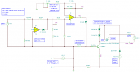
What can you do with the output signal from this plugin? Well, the AV jack output isn't all that high in voltage - I haven't measured it by I believe the maximum Vp-p is about 1-1.2 volts and the current drive capability is likely limited. Some external circuitry will be needed before it can do anything useful. Once I had the plugin working successfully, I designed a simple circuit that uses an active full-wave rectifier plus gain stage feeding a transistor that drives the coil of a relay. When the square-wave signal is received by this circuit, the relay is triggered. Using some high-sensitivity 12Vdc relays, the circuit can operate from a single-ended DC supply of as little as 6-7 volts or higher. It just so happens that I have a bunch of audio power supplies that have a 7.5Vdc aux output that will be perfect for this purpose.
With two on-off delay lines available via the Pi's AV jack I can envision switching on the amplifiers with one channel, and then slightly later un-muting the connection between the DACs I am using and the amplifiers, or alternately the connection between the amplifiers and the speakers. In this way I can turn on the amplifiers only when needed, and I can wait until any startup transients have passed before connecting the amps to the drivers. Another possibility would be to use one channel for switching on the AC mains to the amplifier's power supply and the other channel for switching a soft-start impedance out of the AC line slightly later. After audio is no longer present these actions can be reversed with whatever timing is desired. In reality there are lots of uses for this kind of on/off delay switching. If more channels are needed, one can simply add another inexpensive DAC to the Pi because the hardware requirements are very low. For instance a very inexpensive 6-channel (5.1 audio) DAC would provide 6 independent on/off delay lines.
I'm finally revisiting this sub-project now that some other things have settled down a bit. As I explain above, I would like to switch an external line/signal via a relay. Back when I made the above post, the idea was to use a special LADSPA plugin that I wrote that can monitor the audio stream and generate a square wave output that would be sent to the onboard audio output or via a cheap DAC to an external circuit. The circuit consists of an op-amp active rectifier and a gain stage with a few additional components for smoothing the signal. Following the gain stage is a transistor driver for a relay with some coil back EMF suppression. The gain stage has adjustable gain. I realized that this circuit could be used not only for the square wave output that I originally envisioned for the otherwise unused Pi audio out, but it could also be driven by a logic signal if the gain stage gain was reduced to suit.
The result is shown in the attachment. The op amps are single supply SOT package dual types that cost about 75 cents each in quantities of 10 at Mouser. I happen to have a gross or two of some 12V relays that I want to use, so I will probably design a PCB for them.
One interesting use for this circuit is with the Abletec power supplies that are currently available from various sellers. These include a 7.5V aux supply and that happens to be enough to drive the 12V relays that I have lying around. The relay contacts can be connected to the standby pin on the Abletec supplies so that the circuit can be used to control the HV rails (turn them on and off). The idea is that the Pi, which is always running, would sense audio via my LADSPA plugin, send the square wave signal or toggle a GPIO pin, and then turn on the HV rails (and therefore the amplifiers). Its a great remote on/off solution. When signal is received by the board switching occurs in 10msec to 50msec depending on the gain and the on/off threshold.
You may ask why I would bother to make such a circuit when there are lots of relay board floating around on Ebay and so on. It turns out that these are typically 5V logic driven (the Pi GPIO pins are 3.3V for instance) and have "backwards" logic in that the pin must go lo to trigger the relay. This means when you apply power the relay actually triggers until you can apply a logic HI signal to turn it off. I would rather that my relays just sit there doing nothing while everything powers up and initializes and then I can apply a signal to turn it on. Also, when power is removed, the relay may do some odd things depending on which supply decays first. My approach would allow the relay to behavior to be a little more forgiving.
Another feature of the design is that the power supply for the op-amps and transistor are separate from the power that is used to drive the relay coil. This would mean that other relays with different coil voltages could be easily substituted if/when desired. For instance USB power could be used for the op-amps (yes it works on 5V single supply) while 12V or 24V are used for the relay PS. The op-amp side current requirements are low, so they could be driven from the 5V available on board (of the Pi for example) while the relay needs more current than the Pi should be asked to give, so a separate supply can be used for that. Again, the Abletec PS has a 7.5V aux supply that would be perfect for a high sensitivity 12V coil relay or two.
I like the flexibility of being able to interface with various input signals. The circuit could be used with a computer that doesn't have GPIO type pins available. For instance I own a couple of small Baytrail mini-ITX form-factor mother boards. I can use a cheap USB PCM2704 based DAC ($10 on Ebay!) and this circuit to add a relay interface that I can control from LADSPA to sense the presence of audio and perform an action.
I welcome your input and any feedback if you feel something can be improved, etc. Thanks.
Attachments
Last edited:
I have a nascent layout done. No routing yet, but I can see by the ratsnest that it won't be too bad. I used mostly thru-hole parts, except some active components that are only available in SMD packages.
I added an LDO regulator to the op-amp power supply. The purpose of this is as a limiter for the output of the gain stage (second amplifier). Even if you over drive the circuit, the ultimate voltage output is limited to the rail voltage, which is set by the LDO. This makes the circuit more tolerant to user error, and leaves only the gain adjustment for the user to make, which is very simple to do.
Exciting 3D pic of layout is attached.
Attachments
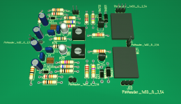
I've managed to route the board. There are two independent relay circuits, since that seemed more practical. A number of inexpensive 1 Form C (SPDT) relays can be used including the cheap SONGLE SRD-12VDC-SL-C. I already have several uses in mind for this...
The 3D view is shown in the attachment.
The 3D view is shown in the attachment.
Attachments
Last edited:
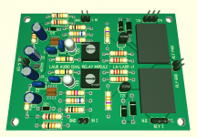
All done. I submitted an order for 20 boards to my usual supplier. I think this is going to be a great addition to my toolbox, and I can finally make use of some of those relays that I have horded!
Below is a 3D model view of the final (version 1) board, populated. The relays are not as tall as they actually are in real life (they are about as tall as they are wide, 12mm or so) but you get the idea.
.
Below is a 3D model view of the final (version 1) board, populated. The relays are not as tall as they actually are in real life (they are about as tall as they are wide, 12mm or so) but you get the idea.
.
Attachments
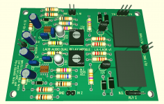
Boards have arrived! I now get to start doing some SMD soldering... it's my first design with SMD parts (even though there are only three of them).
I placed a relay on the board as an example. I hope to get the first board assembled and tested over the next week or so - I am still waiting for some parts that should arrive the day after tomorrow.
Pic attached.
.
I placed a relay on the board as an example. I hope to get the first board assembled and tested over the next week or so - I am still waiting for some parts that should arrive the day after tomorrow.
Pic attached.
.
Attachments
Last edited:
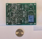
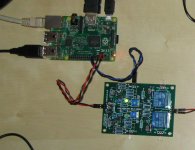
I finished assembling a relay board a couple of days ago and finally got around to testing it today.
The board is paired with a Raspberry Pi with the control circuit powered from the Pi's header: 5V (pin 4) and GND (pins 6). I connected the control input from GPIO 17 (pin 11) and GND (pin 9). A separate 12V DC wall wart is also connected to drive the relay coil(s). You can find a layout of all the header pins from the Raspberry Pi here:
http://data.designspark.info/uploads/images/53bc258dc6c0425cb44870b50ab30621
To toggle the GPIO pin I used the WiringPi library. I found that a simple bash shell script is included with the library that switches GPIO 17 from high to low every 500 msec. This used for the "hello world" script of the Wiring Pi library in which you connect an LED and a current limiting resistor and blink it. I just used this to switch the relay control input on and off.
After adjusting the gain, I found that it works like a charm. In the picture you can see the green LED of one of the channels lit up. You can't see it, but the relay dutifully engaged and disengaged with a click. I felt like I had just made a great automobile turn signal!
Since I can interface this with my LADSPA plugins, I can now control the relay any way I want, specifically based on the presence or absence of an audio signal, to provide turn-on and delay-off behavior for the amplifier power supply. I could also program other behavior - for instance delay-on, zero-delay-off would be useful as a soft-start or for waiting a few seconds after power-up before connecting the amp to the speakers.
Next step is to test with a square-wave control input. I have a suspicion that I may need to increase drive current to the transistor, but so far I'm very happy with the result!
.
Attachments
Last edited:
More testing...
I needed a quick way to output a square wave signal on the Pi's headphone jack. I found that I could generate a wav file on audiocheck.net that I could download. Using the VLC player I could send this to the headphone out. I had to first reconfigure the audio output of the Pi to be sent to the TRRS jack instead of to HDMI using raspi-config. I confirmed that the file playback indeed produced audio in my headphones, disconnected the headphones, and connected the output of the TRRS jack to the relay board control input.
Nothing.
Didn't work!
Hmmmm...
I shut the Pi down for the night, thinking that I should sleep on it and debug in the morning. Then I realized that I hadn't checked the gain level in ALSA... I powered the R-Pi back on and, sure enough, when I checked the level using alsamixer it was set to 40%. I raised the level to 100% and reconnected everything. When I fired up VLC and played the file...
SUCCESS! 😀
I had to make an adjustment of the gain to about the max, but this was expected.
I did have one observation - I think that the op-amp I am using has pretty bad rail-sticking behavior on the output. The op-amp itself is rail-to-rail (within about 20-50mV) capable, and with the gain turned up I am driving the output into full saturation at the rail voltage. When the control input signals that the relay should turn off, there is a small delay of about 500msec during which time the series LED fades and the relay finally releases as the LED goes out. This seems like rail sticking to me. When I back off the gain so that the relay is just engaging when the control input goes active, the relay and LED turn off pretty much instantaneously (judging by eye). Since the delay isn't all that long and shouldn't impact the typical usage I'm not worried about it.
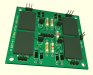
Now that I have had a chance to try the WiringPi library I realized that it's very easy to use, and that the Pi has quite a few GPIO pins available. I decided to design another relay board designed exclusively for control via the GPIO pins of the Raspberry Pi, which allowed me to eliminate most of the circuitry I added to make the relay board able to interface with the square wave signal. After some redrawing I managed to come up with a board layout that can accommodate up to 4 relays in a footprint of only 2.5x2.8 inches. A 3D model of the board from my CAD program is attached. I plan to make a run of these boards soon.
I then turned my focus to the LADSPA plugin that will control the GPIO pins. I haven't publicly released the code for this plugin but I have described it previously. In brief, it monitors the audio signal and takes action when the peak audio level within one buffer frame exceeds or does not exceed a user defined threshold. The plugin allows the user to set separate delays for the on and off action that is taken.
I have started to rewrite the plugin to use the WiringPi library to toggle GPIO pins. The user can specify up to 7 pins to toggle from the same plugin (sharing the same on-delay or off-delay characteristics). For instance, in an N-way loudspeaker you might connect the relays between the amp and each driver, so you need N different relays activated at the same time. Additional relays might control the power supply, muting, or other functions with other timing behavior - multiple instances of the plugin are used when different on or off behavior is needed.
I'm also thinking of incorporating an optional delay-and-fade-in behavior when the output changes from the "off" state to the "on" stage. For instance, when you want to trigger the speaker relays to connect the amp(s) and driver(s), you might want the audio signal to be muted for a second and then ramp up in volume over 2 or 3 seconds. This behavior would be specified by the user, or could be bypassed entirely. This would help to create a graceful turn-on of the audio output from the loudspeaker.
Once I get the code debugged and working I plan to release it as part of an update to my LADSPA plugin package. I also need to get started writing some documentation that will make it easier for people to understand how to put my LADSPA plugins to use in their own projects.
Attachments
Thanks!Nice! I like the way you work.
Just spent the last few hours debugging the code for the new plugin. It now seems to be working well. I did some listening through headphones while I tested out the various features and I really like the fade-in capability when the system is turning itself on. It makes for a very graceful entry...
For the GPIO pin changes, I ended up modifying my approach. I'm still using the wiringPi library but discovered that the code-based approach results in code that has to be run as superuser! That's not really viable for a LADSPA plugin, so I started looking for an alternative. It turns out that the recent the wiringPi relase includes a command line utility that does not need to be run as superuser. In fact that was what I was using to test out the first board that I developed (see above). wiringPi now comes are part of the Raspbian distro, at least the recent version that am using (dated March 10, 2016), and runs on and is portable between both the Pi 2 and Pi 3. My code makes a system call to the gpio command line utility from within the LADSPA plugin. The overhead of a system call does briefly increase the CPU usage, but since this only happens once at turn-on and once again at turn-off or if an interrupt is sent (e.g. control-C) I'm not too worried about it. CPU usage when running is 1% on a Pi2. Using this approach really helped me keep it simple from the programming side.
You can read about the wiringPi gpio utility here:
The GPIO utility | Wiring Pi
with some example code to toggle GPIO pins here (info is slightly dated):
RPi GPIO Code Samples - eLinux.org
note that you no longer have to downlaod and install the gpio utility - it's provided as part of the Raspbian OS.
Last edited:
Adding a couple more bits of information:
I decided to break out the code that calls the system shell commands that manipulate the GPIO pins into a couple of small functions. Although I have used a Raspberry Pi specific shell command, it's just a concatenation of text and numbers. The same approach can be used to form any sort of text based commands (including multiple lines of shell commands) that are then executed on the system. In this way the functions can easily be modified for other Linux systems that can somehow toggle GPIO pins that are part of, or attached to (e.g. USB based GPIO add-on boards), the system. For example, this FT232H board is a USB dongle with several GPIO pins onboard:
Adafruit FT232H Breakout - General Purpose USB to GPIO+SPI+I2C
Since the plugins are supplied as code, the user can simply modify the functions if they need to tweak how the GPIO manipulation is done. This makes the code easy to adapt to different hardware, or to adapt it to future changes in OS GPIO interfacing.
The other feature that I have added on is a "latency" parameter. I envisioned the possibility that the LADSPA code might toggle the relay at "turn-on" faster than the audio chain can be processed by the host (e.g. LADSPA). This could result in undesired behavior, e.g. a turn on happening a few tens or 100 msec before it is supposed to, because of the processing latency. The user supplied value is only used to delay the GPIO change to the HIGH state. This value can be set to the processing latency, or a slightly longer time period, to ensure that the order of operation is correct.
I've been continuing to test the code. Smooth sailing, so I think it's pretty much ready...
That is except for the fact that I realized that I could just use the native Linux GPIO control that is built into the kernel instead of the Raspberry Pi specific wiringPi routine. To learn more, read these links:
Access GPIO from Linux user space | FalsinSoft
https://www.kernel.org/doc/Documentation/gpio/sysfs.txt
The advantage of toggling GPIO pins via the kernel interface is that it's not Raspberry Pi specific. It also does not need to be run as superuser (at least on my R-Pi). Another advantage is that systems with ad-on GPIO hardware can gain control of them via this technique.
The disadvantage is that I still can only pass single digits 0-9 (up to seven of them) into the plugin to indicate which GPIO to toggle. As a result, I need to introduce a "map" array that defines the relationship between the index (e.g. 0-9) and the actual GPIO number (e.g. 17, 23, etc.). If one or more new GPIO pins need to be controlled the code must be edited, the new "mapping" defined, and the plugin ".so" file re-made. This approach is more involved, but this will increase flexibility and seems to be completely worthwhile.
I will distribute the plugin with the map set up for some otherwise unused GPIO pin numbers on the Raspberry Pi and will provide instructions on how to edit the map in code if and when that is desired.
- Home
- Source & Line
- PC Based
- LADSPA plugin programming for Linux audio crossovers