Well, that wasn't so bad... I implemented the new scheme and it works just fine. It's slightly more complicated in code, but will allow my friends using the BBB or other non-R-Pi Linux systems to use this plugin.
I will continue to do testing over the weekend.
I will continue to do testing over the weekend.
I finished writing the documentation for the new OnOffDelay plugin and I have released this along with a couple other minor updates and fixes to my other plugins on my web page. A direct link is in my signature, or you can click on "LADSPA plugins" here: audio.claub.net Software Page
OnOffDelay LADSPA plugin Programmer Notes:
Overview:
The purpose of this plugin is to control one or more GPIO outputs
with on-delay and off-delay behavior under a linux OS. When entering the
'on' state, the plugin sets one or more GPIO pins to 'high'. When entering
the 'off' state, these same GPIO pins are set to 'low'. The GPIO pins can
be used to trigger external equipment like relays, put amps or power supplies
into standby, etc. The plugin monitors each of two (e.g. stereo) inputs.
Audio Trigger Threshold:
The plugin's two audio inputs are both analyzed and used to trigger the
on-delay and off-delay behavior of the output. The peak level of the input
(e.g. audio signal) is monitored and compared to a reference level called the
'Threshold', specified in dB below maximum. When the peak level within a
frame exceeds the threshold, a timer is started. As long as the peak signal
level continues to exceed the Threshold the timer will count up. When the
timer exceeds the value for the plugin's DelayON parameter the output is set
to 'on'. Similarly, when the peak level within a frame does not exceed the
threshold, a timer is again started. As long as the peak level continues to
be below the Threshold for each frame, the timer will count up. When the
timer exceeds the value for the plugin's DelayOFF parameter the output is
set to 'off'.
Options for Audio Signal Behavior at Turn-On:
The plugin has the ability to first mute and then fade-up the audio level
when 'turning on' the output after the DelayON period has completed. The
duration of the muting and fade-in are both specified through a real-
valued parameter in the format of M.F, where M is the number of seconds the
audio signal should be muted and F is the number of seconds over which the
fade-in should take place. M.F is a real number with digits to the left and
right of of the decimal point. For example, 3 seconds of muting followed
by two seconds of fade-in would be provided as the parameter '3.2'. The
signal fades in from the level set by the Threshold parameter to the full
level over the number of seconds indicated. M and F are given in increments
of whole seconds due to the integral nature of the M.F representation. An
unlimited number of seconds of muting and up to 9 seconds of audio fade-in
can be specified in this way. If no muting or fade-in at turn-on is desired,
simply supply the value 0.0 or omit the parameter entirely.
Accounting for System Latency / Delaying the change to HIGH state:
There will be some finite time that elapses between when the code runs to
process a block of audio and when that very same audio signal is produced
at the output (e.g. at the DAC output). In the case of a relay used to
disconnect the speaker from the amplifier, the stress on the contacts are
minimized if the changeover ocurrs when the audio is muted and no voltage
exists across the contacts. The value supplied for the latency adds the
specified amount of delay (in seconds or fractions of a second) to the GPIO
pin state change when going from LOW to HIGH. This can be used to insure
that the GPIO pin state change happens only after the audio signal at the
DAC output is muted.
Controlling Multiple GPIOs simultaneously from the same plugin instance:
From one to seven GPIOs can simultaneously be turned on (HIGH logic state) or
turned off (LOW logic state) from the same plugin. The user provides the
plugin with a number which is a concatenated list of one or more indexes. The
default index is 0. If no index is supplied, the GPIO for index 0 is used.
If index 0 is used in a list, it must come after at least one non-zero index
(e.g. zero cannot be the first digit). For example, if the user wishes to
toggle the GPIOs corresponding to indexes of 0,2,3 and 7 then 7320 would be
provided as input to the plugin. All are turned on and off simultaneously.
Specifying GPIO pins via the 'index_to_GPIO_map' array:
The user tells the plugin which GPIO(s) should be controlled using an index
(0..9). Internally, the 'index_to_GPIO_map' array is used to translate the
index to the actual GPIO number on the computing hardware. The plugin code
has been provided with a set of otherwise unused GPIOs for the Raspberry Pi
models 2 and 3. The 'map can be changed to control other GPIOs and for other
computing hardware by editing the entries in the 'GPIO#' column in the code.
I am curious what kinds of measurement software you folks are using to validate your crossover designs? I have been using Room EQ Wizard and finding it to have poor reproducibility with my system (BBB running XO filters in ALSA). I am using REW on a macbook pro. I use a calibrated USB microphone and the signal generator is output to the BBB via either USB or AirPlay. My scans are coming back with unacceptable variation. My specific complaints are:
1. The REW signal generator apparently is causing inaudible oscillation probably in the I/V stages for the es9018 DACs. ...or maybe just in the amps, but either way the amps all heat up progressively in silence while the REW window is open. This has only ever happened with REW, never any other signal source. The hotter the system gets, the more obvious are frequency 'dropouts' at 340 and 680 Hz. Bottom line, I can't really evaluate a 'steady-state'.
2. I can control the output volume of the sweep at the source (macbook) or at the destination (es9018 volume registers - 48 bit precision). With the needed attenuation equal, but provided by one or the other source, the scan results differ significantly. Whazzup with that???
3. I can hear obvious harmonic distortions in the frequency sweeps unless the gain is below about -10 dB.
I tried creating the sweep in SoX and recording and graphing it in REW but the calibration is way off... Anybody have experiences or suggestions?
TIA,
Frank
I've used ARTA in dual channel mode - this allows the user to account for the system latency. I have also used ARTA's gated impulse frequency response mode, but I found that when using a single channel input sometimes the beginning of the impulse would get cut off unless I made that as long as possible.
I have only used REW when doing THD measurements with a fixed frequency sine excitation so I can't comment on its measurement procedure under other conditions.
If you have boost above 10dB and you use an input level above -10dB you will probably get digital clipping at the DACs. You might check for that.
Hi,
I have played with LADSPA plugins during all the week-end. My purpose is to implement active filters initially designed fort miniDSP in software DAS on a Linux machine (TBD).
Thanks Charlie's tools and tutorials from Richard Taylor, I succeeded to do mimic miniDSP initial filters in LADSPA as of frequency response. Tweaking some frequencies for shelf filters (thanks Charlie for your help) and Q factors for PEQ is needed, but with some trials and errors this can be easily solved.
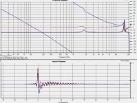
I was happy untill I looked at the phase response. They don't look the same even for very basic filters. My very basic understanding of filters and DSP does not allow me to go forward. Help welcomed. I attach some examples.
The measurements are done with HomImpulse.
In blue, the mini DSP, the loop physically goes from soundcard output => miniDSP => soundcard line input.
In red, the ACDf / LADSPA filters: The HomImpluse measurement signal is fed to ecasound/LADSPA filters => output file. Then the measurement signal file and resulting file are imported in HolmImpulse, and compared to the miniDSP. The Db offset is compensated manually.
Kind regards,
JMF
I have played with LADSPA plugins during all the week-end. My purpose is to implement active filters initially designed fort miniDSP in software DAS on a Linux machine (TBD).
Thanks Charlie's tools and tutorials from Richard Taylor, I succeeded to do mimic miniDSP initial filters in LADSPA as of frequency response. Tweaking some frequencies for shelf filters (thanks Charlie for your help) and Q factors for PEQ is needed, but with some trials and errors this can be easily solved.
I was happy untill I looked at the phase response. They don't look the same even for very basic filters. My very basic understanding of filters and DSP does not allow me to go forward. Help welcomed. I attach some examples.
The measurements are done with HomImpulse.
In blue, the mini DSP, the loop physically goes from soundcard output => miniDSP => soundcard line input.
In red, the ACDf / LADSPA filters: The HomImpluse measurement signal is fed to ecasound/LADSPA filters => output file. Then the measurement signal file and resulting file are imported in HolmImpulse, and compared to the miniDSP. The Db offset is compensated manually.
Kind regards,
JMF
Attachments
What I see in red looks correct to me.
In the first (left) plot, you have two PEQ bands. The phase response for a PEQ is exactly what is shown in red. For the miniDSP measurements you have additional phase rotation. I'm not sure where this is coming from - it doesn't look like frequency-independent delay to me, since that would increase in slope with frequency. I don't want to say that something is "wrong", but that really should not be there. The LADSPA filter phase, and frequency response, is correct.
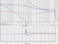
In the second plot the phase again looks correct for the LADSPA filters. But I see something else in the miniDSP and LADSPA impulse responses. They have a component at low frequency that is about the same in magnitude, but of opposite polarity. I can make out the following:
Keep in mind that you took measurements through and ACD and a DAC for the miniDSP system, while neither an ACD or a DAC are in the signal path for the LADSPA measurement. These additional signal processing operations (A to D and D to A) can have their own filters, e.g. anti-aliasing filters, ultrasonic LP and infrasonic HP.
You might measure both systems when they are set "flat", that is no user filters in the chain.
In the first (left) plot, you have two PEQ bands. The phase response for a PEQ is exactly what is shown in red. For the miniDSP measurements you have additional phase rotation. I'm not sure where this is coming from - it doesn't look like frequency-independent delay to me, since that would increase in slope with frequency. I don't want to say that something is "wrong", but that really should not be there. The LADSPA filter phase, and frequency response, is correct.
In the second plot the phase again looks correct for the LADSPA filters. But I see something else in the miniDSP and LADSPA impulse responses. They have a component at low frequency that is about the same in magnitude, but of opposite polarity. I can make out the following:
- The miniDSP system seems to have pre- and post- ringing. This might be due to some FIR component to the system (as part of the input filters for instance).
- The largest spike in both the LADSPA and miniDSP impulses seems to be about the same in magnitude and the responses look the same.
- There is a lower frequency component that produces the slowly dying tails of each impulse. This might be the DC-blocking highpass filter response. For the LADSPA impulse this initially rises up and then decays away, and the response looks critically damped (Q=0.5). For the miniDSP impulse it does the opposite - it initially falls and then slowly rises (the decay is rising back to "zero") and because it crosses "zero" and then falls back it is probably Q=0.707.
Keep in mind that you took measurements through and ACD and a DAC for the miniDSP system, while neither an ACD or a DAC are in the signal path for the LADSPA measurement. These additional signal processing operations (A to D and D to A) can have their own filters, e.g. anti-aliasing filters, ultrasonic LP and infrasonic HP.
You might measure both systems when they are set "flat", that is no user filters in the chain.
Well, what would be the result with minidsp applying a dummy filter, or no filter at all? 🙄
I don't remember how close to a dirac looked the last loopback measurement i made with whatever soundcard i owned... Pre and post response, always some as far as i remember...😱
Btw, the phase response in blue looks like a bandpass 20-20000hz inverting filter, "centered" hence shifting around 1Khz, . Removing the inversion would remove the phase shift. In the red curve there is no such inversion, nor bandpass effect added to the correction.
Last edited:
I did some comparisons in REW a while ago comparing a LADSPA LR lowpass filter with the built in DSP lowpass in a Crown XLS2000 amp. I think it was a 4th order. The results were more or less identical.
Since I never figured out how to get the USB mic to connect directly to the RPI, and didn't want to have any buffer or latency issues by connecting other computers, I have been testing my filters using an old netbook so I can connect USB mic and USB Dac to the same computer.
Yes, be careful checking the input signal to make sure it doesn't clip. Try for example -eadb:-10.0
R Taylor outputs it to a wav file to be able to inspect it:
I have been using ecasound's built in signal analysis tools to figure it out:
"SIGNAL ANALYSIS
-ev Analyzes sample data to find out how much the signal can be
amplified without clipping. The resulting percent value can be
used as a parameter to -ea and -eas effects. Also prints a
statistics table containing info about stereo-image and how
different sample values are used.
-evp Peak amplitude watcher. Maintains peak information for each pro-
cessed channels. Peak information is resetted on every read.
-ezf Finds the optimal value for DC-adjusting. You can use the result
as a parameter to -ezx effect."
Link: ecasound
Since I never figured out how to get the USB mic to connect directly to the RPI, and didn't want to have any buffer or latency issues by connecting other computers, I have been testing my filters using an old netbook so I can connect USB mic and USB Dac to the same computer.
Yes, be careful checking the input signal to make sure it doesn't clip. Try for example -eadb:-10.0
R Taylor outputs it to a wav file to be able to inspect it:
Code:
ecasound -i:alsa,hw:Device -o:output.wavI have been using ecasound's built in signal analysis tools to figure it out:
"SIGNAL ANALYSIS
-ev Analyzes sample data to find out how much the signal can be
amplified without clipping. The resulting percent value can be
used as a parameter to -ea and -eas effects. Also prints a
statistics table containing info about stereo-image and how
different sample values are used.
-evp Peak amplitude watcher. Maintains peak information for each pro-
cessed channels. Peak information is resetted on every read.
-ezf Finds the optimal value for DC-adjusting. You can use the result
as a parameter to -ezx effect."
Link: ecasound
Last edited:
Hi,
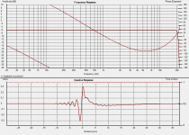
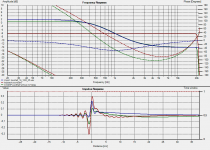
Thank you all for all the thoughts and analysis you provided. This helped. It first reminded that in some of the miniDSP measurements I had a signal inversion and a delay, that I didn't programed yet in LADSPA filters. I also remeasured the soundcard loopback phase, and bingo. See attachment.
I will wait to finalize my speakers and then make real speaker measurements, with similar measurement chain, which is not the case yet (soundcard for the miniDSP, and pure calculations for the LADSPA filters).
Thanks for the help,
JMF
JMF
Attachments
Last edited:
I'm trying something new with LADSPA that I have avoided (like the plague) in the past: implementing LADSPA filters under ALSA! 😱
Thanks to some very persistent and hard work by users francolargo and jrubins I have some useful templates to work from. Using THIS ALSA CONFIG posted by jrubins for the R-Pi I have started to develop my own simply application.
What I would like to do is connect a miniStreamer to the R-Pi. The miniStreamer has full duplex SPDIF input and output at up to 24/96. Unfortunately I cannot know in advance what sample rate the user might supply to the input spdif line, so it is impossible to use e.g. ecasound which requires the sample rate to be known in advance. But it seems that, using ALSA as a LADSPA host, I will be able to input, process, and then output whatever sample rate digital audio is supplied to the unit.
Unlike a full blown loudspeaker crossover I only need a single LADSPA plugin implemented for each of two stereo channels. This seems to make things a lot more straightforward under ALSA, or at least I think so. I am posting below what I think would be the ALSA .asoundrc file for such a setup. I have used a generic name of "SomeFilter" in place of whatever plugin I end up using, and provided dummy parameters.
If either francolargo or jrubins can comment on this, or anyone else who has mastered ALSA, I would be very grateful. I will also try it out here, but if it doesn't work I don't really know how to debug such a thing...
Proposed 2-ch (stereo) LADSPA plugin implementation
So, this is much abbreviated compared to an actual crossover application. If I understand correctly, because I am simply implementing a filter on each channel and just passing that from input to output I don't need a t-table. Not sure...
The other question is how exactly the input coming FROM the miniStreamer will be routed through all of this... does it do that automatically because this has been labeled as the "default" ALSA plug? And then how does it get routed back TO the miniStreamer spdif output?
Thanks to some very persistent and hard work by users francolargo and jrubins I have some useful templates to work from. Using THIS ALSA CONFIG posted by jrubins for the R-Pi I have started to develop my own simply application.
What I would like to do is connect a miniStreamer to the R-Pi. The miniStreamer has full duplex SPDIF input and output at up to 24/96. Unfortunately I cannot know in advance what sample rate the user might supply to the input spdif line, so it is impossible to use e.g. ecasound which requires the sample rate to be known in advance. But it seems that, using ALSA as a LADSPA host, I will be able to input, process, and then output whatever sample rate digital audio is supplied to the unit.
Unlike a full blown loudspeaker crossover I only need a single LADSPA plugin implemented for each of two stereo channels. This seems to make things a lot more straightforward under ALSA, or at least I think so. I am posting below what I think would be the ALSA .asoundrc file for such a setup. I have used a generic name of "SomeFilter" in place of whatever plugin I end up using, and provided dummy parameters.
If either francolargo or jrubins can comment on this, or anyone else who has mastered ALSA, I would be very grateful. I will also try it out here, but if it doesn't work I don't really know how to debug such a thing...
Proposed 2-ch (stereo) LADSPA plugin implementation
Code:
#based on asound rc new version jrubinstein - experimental with charlies plugin
#source: [url]https://github.com/jrubinstein/raspiDSP/blob/master/alsa%20configuration%20asoundrc-experimental2.cpp[/url]
pcm.!default {
     type plug
     slave.pcm myfilter
}
ctl.!default {
     type hw
     card 0
}
pcm.myfilter {
     type ladspa
     path "/usr/lib/ladspa"
     channels 2
     plugins
     {

        0 {
               label SomeFilter
               policy none
               input.bindings.0 "Input"
               output.bindings.0 "Output"
               input { controls [1 2 3 4 5 6 7] } #dummy parameters
        }
        1{
               label SomeFilter
               policy none
               input.bindings.1 "Input"
               output.bindings.1 "Output"
               input { controls [1 2 3 4 5 6 7] } #dummy parameters
        }
pcm.plughw.slave.rate = "unchanged";
So, this is much abbreviated compared to an actual crossover application. If I understand correctly, because I am simply implementing a filter on each channel and just passing that from input to output I don't need a t-table. Not sure...
The other question is how exactly the input coming FROM the miniStreamer will be routed through all of this... does it do that automatically because this has been labeled as the "default" ALSA plug? And then how does it get routed back TO the miniStreamer spdif output?
Last edited:
I have been experimenting over the last couple of days and I have found a solution to my problem that does not involve ALSA: Sox!
With Sox I have been able to read the incoming spdif stream, apply a LADSPA plugin, and then send the resulting audio out as spdif. This is nice - it's something that could be inserted inline in a coax spdif line to apply a LADSPA chain to the signal. There is no limit to the number of LADSPA plugins that can be applied (only by the capabilities of the hardware). I don't think that Sox can easily branch and loop the data stream, so it is not going to replace ecasound in my tool box. But it has filled my need nicely.
Here is an example command line:
-b specifies the bit depth of the audio
-r specifies the sample rate of the audio
-t specifies the data format, with the device for sourcing/sinking audio immediately following
The above command is calling sox to process a 16-bit, 96kHz audio stream, reading in from an ALSA device (the spdif input), sending out at 16/96 to an ALSA device (the spdif output) and a LADSPA filter is applied to the signal within Sox. This particular filter is a bass boost of 12dB below 120Hz using a 2nd order shelving filter.
This seems to work pretty well. Latency is very low. CPU utilization is only about 7-8%.
Unfortunately I was not able to achieve one of my original goals: processing a number of different spdif formats without knowing in advance the bit depth and sample rate of the audio. This limitation seems to primarily be due to the USB interface of the miniStreamer - it doesn't pass the info to the computer. Instead the computer sets these parameters and then attempts to fetch the data from the USB interface.
For now this is mostly working, as long as I can change the command line in response to different spdif formats. I could try to discover the bit depth and sample rate of the spdif stream outside the R-Pi and pass that info to the Pi via GPIO pins or an I2C line. For instance, some spdif RX chips make this info available, but I would need to design a PCB for this. Discovering the sample rate alone could be done using a frequency counter on a GPIO pin that is connected to the word clock (LRCLK) that the miniStreamer makes available on a header pin. By counting the frequency of the LRCLK I should be able to immediately know when the sample rate has changed.
Finally, there is a limitation to the USB bus for spdif audio. Under USB high speed, the bus cannot handle duplex 24/96 data transfer without bonking. 16/96 works fine, however, and that is the reason that I have used that spec in my command line. A workaround for this might be to use a DAC or DIGI hat for the Pi that will send out the data via I2S instead of the USB bus. That should provide duplex 24/96 audio, although I have not yet tested it.
With Sox I have been able to read the incoming spdif stream, apply a LADSPA plugin, and then send the resulting audio out as spdif. This is nice - it's something that could be inserted inline in a coax spdif line to apply a LADSPA chain to the signal. There is no limit to the number of LADSPA plugins that can be applied (only by the capabilities of the hardware). I don't think that Sox can easily branch and loop the data stream, so it is not going to replace ecasound in my tool box. But it has filled my need nicely.
Here is an example command line:
Code:
sox --buffer 2048 -b 16 -r 96k -t alsa hw:2,0 -b 16 -r 96k -t alsa hw:2,0 ladspa /usr/local/lib/ladspa/ACDf.so 25 0 0 60 0.707 120 0.707-r specifies the sample rate of the audio
-t specifies the data format, with the device for sourcing/sinking audio immediately following
The above command is calling sox to process a 16-bit, 96kHz audio stream, reading in from an ALSA device (the spdif input), sending out at 16/96 to an ALSA device (the spdif output) and a LADSPA filter is applied to the signal within Sox. This particular filter is a bass boost of 12dB below 120Hz using a 2nd order shelving filter.
This seems to work pretty well. Latency is very low. CPU utilization is only about 7-8%.
Unfortunately I was not able to achieve one of my original goals: processing a number of different spdif formats without knowing in advance the bit depth and sample rate of the audio. This limitation seems to primarily be due to the USB interface of the miniStreamer - it doesn't pass the info to the computer. Instead the computer sets these parameters and then attempts to fetch the data from the USB interface.
For now this is mostly working, as long as I can change the command line in response to different spdif formats. I could try to discover the bit depth and sample rate of the spdif stream outside the R-Pi and pass that info to the Pi via GPIO pins or an I2C line. For instance, some spdif RX chips make this info available, but I would need to design a PCB for this. Discovering the sample rate alone could be done using a frequency counter on a GPIO pin that is connected to the word clock (LRCLK) that the miniStreamer makes available on a header pin. By counting the frequency of the LRCLK I should be able to immediately know when the sample rate has changed.
Finally, there is a limitation to the USB bus for spdif audio. Under USB high speed, the bus cannot handle duplex 24/96 data transfer without bonking. 16/96 works fine, however, and that is the reason that I have used that spec in my command line. A workaround for this might be to use a DAC or DIGI hat for the Pi that will send out the data via I2S instead of the USB bus. That should provide duplex 24/96 audio, although I have not yet tested it.
Last edited:
The above approach can be used with other linux audio programs. For example using ecasound the following command is equivalent to the sox implementation given above:
CPU utilization is exactly the same as with sox.
Ecasound is IMHO a very good platform for implementing loudspeaker crossovers. One could use the miniStreamer's spdif input, implement the loudspeaker crossover (2-way in this case) in ecasound, and then connect a DAC with an spdif input to the miniStreamer's output.
Code:
ecasound -b:2048 -f:16,2,96000 -i:alsahw,2,0 -el:ACDf,25,0,0,60,0.7,120,0.7 -o:alsahw,2,0Ecasound is IMHO a very good platform for implementing loudspeaker crossovers. One could use the miniStreamer's spdif input, implement the loudspeaker crossover (2-way in this case) in ecasound, and then connect a DAC with an spdif input to the miniStreamer's output.
Unfortunately I was not able to achieve one of my original goals: processing a number of different spdif formats without knowing in advance the bit depth and sample rate of the audio. This limitation seems to primarily be due to the USB interface of the miniStreamer - it doesn't pass the info to the computer. Instead the computer sets these parameters and then attempts to fetch the data from the USB interface.
For now this is mostly working, as long as I can change the command line in response to different spdif formats.
A very good start, I think, because I suspect there is a reasonable way to sense the recording stream sample rate. Since a 48kHz input can be up sampled to 96 without sonic penalty, the issue is only to distinguish between multiples of 44.1kHz and 48 kHz. So I will mess around in my BBB system to see if somehow the Botic kernel is aiding in that regard. Obviously, the kernel needs to sense the input parameters in order to choose the correct external clock. I'll use my little UA-25EX to generate 44.1 SPDIF and see what I can learn.
Cheers!
Speaking of the sample rate... You simple need to differentiate between all possible rates. In this case the max rate that can be accommodated is 96kHz, and below there is only 88.2k, 48k and 44.1k for audio. So you need only to be able to differentiate these.
It turns out that the pigpio library (now included with the Raspbian OS distro) includes a couple of short C programs that do frequency counting as examples of what the library can do. These could be used directly on this problem along with an output from the miniStreamer hardware. The miniStreamer manual shows that the word clock (LRCLOCK) for the I2S version of the spdif input (when miniStreamer is the master clock) is made available on a header pin. The word clock is the same as the sample rate, which is helpful because if we needed to look at the bit clock of the spdif signal itself we would need to measure frequencies up to 6MHz or so. Measuring 96kHz is a much easier task. By connecting the word clock to a free GPIO pin of the Pi and using the pigpio frequency counter program the frequency is updated at the command prompt every N 10ths of a second. This could be incorporated into a shell script that kills and restarts ecasound or sox when the spdif rate (and thus the frequency) changes. This approach would be equivalent to ALSA stopping and restarting a LADSPA plugin automatically when the sample rate changes.
Sorry to post questions instead of answers here. I discover this universe of multiple sample rates and different clocks freqencies (things like 44.1/48...). As I need to develop my ecasoud DSP crossover, and try to decide about my options for a time accurate SBC=>multichannel=>active amps (ideally with I2S inputs), I try to get a correct picture of the thing.
So, my question: How other than ecasound software do normally sense the sampling rate ? I imagine that all music players need to get that info to play/record at the right pace ?
JMF
So, my question: How other than ecasound software do normally sense the sampling rate ? I imagine that all music players need to get that info to play/record at the right pace ?
JMF
Sorry to post questions instead of answers here. I discover this universe of multiple sample rates and different clocks freqencies (things like 44.1/48...). As I need to develop my ecasoud DSP crossover, and try to decide about my options for a time accurate SBC=>multichannel=>active amps (ideally with I2S inputs), I try to get a correct picture of the thing.
So, my question: How other than ecasound software do normally sense the sampling rate ? I imagine that all music players need to get that info to play/record at the right pace ?
JMF
The "Sensing of the sampling rate" depends on things like the Operating System and the way audio is supplied to its audio subsystem.
For instance in Linux there is ALSA. If you play a WAV file, the player gets the info about the bit depth and rate from a header in the WAV file and it will pass that along to ALSA and to a DAC connected to the ALSA system. In my case I am either streaming audio in via ethernet/wifi or a USB spdif dongle. These both supply "raw audio" to the ALSA subsystem, so it has no clue about the format, etc. In that case you need to give the player this information explicitly. For this reason I pick one rate and stick to it, re-sampling if needed.
Mostly if you are playing files or internet streams, the player will know the info about them. If your system is all on one computer you probably will not have any problems.
Perhaps user Francolargo can comment here as well. He is much more familiar with local clocks and I2S than me.
Thank you for the explanation. I had put in my mind that there was an issue with ecasound and sampling rates (from your discussion and Richard Taylor site), but I not identified that it was mainly for SPDIF, and was not an issue for music files, which have an header that contains the information.
Yes, I will be in a config without digital inputs (at the moment) and only considrr playing files.
JMF
Yes, I will be in a config without digital inputs (at the moment) and only considrr playing files.
JMF
Charlie,
I'm working at the moment with your Ladspa filters library, and I have something strange. When I implement an HighShelf using ecasound... -el:ACDf,25,1,8,10071,0.7,6354,0.7 I get something different from what I get in the ACD excel sheet with the same parameters:
- in the excel sheet the difference between the two levels is 8dB as expected,
- but the plugin execution seems to give me a difference between the two levels nearer from10dB (so 2dB difference).
Could I have made something wrong? Specific data to provide to ease the analysis if relevant?
I'm surprised as the LowShelf -el:ACDf,25,1,0,631,0.5,1585,0.5 provided me better consistency.
best regards,
JMF
Can you turn off all other filters and just run this filter, and then provide (upload) a plot of the measurements showing 10dB difference? In the mean time I will check the code and think of why this might happen.Charlie,
I'm working at the moment with your Ladspa filters library, and I have something strange. When I implement an HighShelf using ecasound... -el:ACDf,25,1,8,10071,0.7,6354,0.7 I get something different from what I get in the ACD excel sheet with the same parameters:
- in the excel sheet the difference between the two levels is 8dB as expected,
- but the plugin execution seems to give me a difference between the two levels nearer from10dB (so 2dB difference).
Could I have made something wrong? Specific data to provide to ease the analysis if relevant?
I'm surprised as the LowShelf -el:ACDf,25,1,0,631,0.5,1585,0.5 provided me better consistency.
best regards,
JMF
Also, what sample rate are you using?
- Home
- Source & Line
- PC Based
- LADSPA plugin programming for Linux audio crossovers