Making more progress with the other channel.
On this channel I installed one pair (to start with) of genuine ON NJW0302G and NJW0281G. (Yes, the amplifier blew with four pairs of stock "D1047/B817" outputs and no output signal and powers up fine with just one pair of genuine devices.)
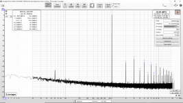
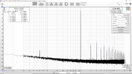
Then I measured distortion (at a fairly low level, 16W) with the "stock" downgrade drivers (picture attached) and then genuine Toshiba 2SC5171/2SA1930. Both are at the same bias level and the distortion is improved.
So perhaps the downgrade drivers is one reason I do not measure the claimed distortion levels. After a break I will continue with more output pairs and see how the distortion responds. For others to install genuine Toshiba 2SC5171/2SA1930 it might require taking apart used gear such as defunct home theater receivers. Expect the ones for sale to be fake. (Discontinued and highly sought after.)
First attachment is the downgrade stock drivers, the second THD with the downgrade drivers and the third is with genuine Toshiba drivers.
On this channel I installed one pair (to start with) of genuine ON NJW0302G and NJW0281G. (Yes, the amplifier blew with four pairs of stock "D1047/B817" outputs and no output signal and powers up fine with just one pair of genuine devices.)
Then I measured distortion (at a fairly low level, 16W) with the "stock" downgrade drivers (picture attached) and then genuine Toshiba 2SC5171/2SA1930. Both are at the same bias level and the distortion is improved.
So perhaps the downgrade drivers is one reason I do not measure the claimed distortion levels. After a break I will continue with more output pairs and see how the distortion responds. For others to install genuine Toshiba 2SC5171/2SA1930 it might require taking apart used gear such as defunct home theater receivers. Expect the ones for sale to be fake. (Discontinued and highly sought after.)
First attachment is the downgrade stock drivers, the second THD with the downgrade drivers and the third is with genuine Toshiba drivers.
Attachments
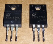
On the stock downgrade drivers does anyone else find it strange that the complementary PNP has a totally different date code/lot code format than the NPN?
Most real semiconductor companies with ISO certification have pretty standardized marking schemes...
Most real semiconductor companies with ISO certification have pretty standardized marking schemes...
A bit less, 53MHz. Look at the snapshot below. As soon as I have increased the bias, oscillations have ceased to exist. Look at the post #22 of this conversation.54 MHz? Nice!
I could use my TinySA to look for that...
Last edited:
So I did a lot more work and I have found that I get better THD with genuine Toshiba 2SC5171/2SA1930 drivers and with Toshiba (Japan) O gain rank 2SC5200 and 2SA1943. (The THD is almost half what I measured with genuine ON Semi NJW0302G and NJW0281G even with genuine Toshiba 2SC5171/2SA1930 drivers from the same batch. I was not expecting that.) The large case Toshiba outputs are hard to fit and I can not install the two screws at the output end of the PCB.
I obtained the genuine Toshiba 2SC5171/2SA1930 drivers by disassembling the left and right channels of an old amp. So both are the same batch and both are genuine.
The attached results are the best that I can achieve at 64W output with the L20.5. These results are similar to what I achieved with the L20 V7 DIY kit (CFP version) which was older and still came with Toshiba 2SC5171/2SA1930 drivers. The L20 V7 was bought a number of years ago now.
I suggest that other L20.5 users get rid of the D1047 B817 outputs (which burn up in my experience) and replace the downgrade drivers with genuine Toshiba. That way you can get the expected low THD performance.
With the +/-56V supplies (112V rail to rail) and 4 Ohm load this 64W test (4 Amps) is fairly hard on the amplifier considering how small the official LJM L20.5 heatsinks are. They get very hot during the test. With the L20.5 surviving my tests (with genuine Toshiba outputs and drivers) I am now hopeful it will also be reliable.
Attachments

Last edited:
I was wondering if anyone can explain why the Toshiba 2SC5200 and 2SA1943 result in so much lower THD than the NJW0302G and NJW0281G? Both L20.5 amplifiers are from the same batch (purchased as a pair), have the same bias and both are using the same Toshiba 2SC5171/2SA1930 drivers (now).
Is it perhaps the 2x higher capacitance of the NJW0302G and NJW0281G? (2SC5200N = 200 pF, NJW0281G = 400 pF)
I ask since I bought some ON Semi NJW0302G & NJW0281G pairs (and some ON Semi NJW1302 & NJW3281 pairs) based upon a number of recommendations they received. However this result is pointing me back to the Toshiba 2SC5200 and 2SA1943 instead.
The D1047/B817 also have lower capacitance however the SOA and/or quality appears to be a real issue with these amplifiers.
Last edited:
I am using the same set of transistors as you do, including MJL1302/MJL3281, but on a different amplifier which can operate in both A and AB mode. It is virtually impossible to distinguish by listening the effect of using different transistors. However, switching to the pure A class offers consistently better results.
Now, my view on the usability of THD measurements based on FFT analysis:
To analyze possible discrepancies we should investigate (or should I say: blame) methodology of THD measurement itself. This method assumes that, according to Fourier, complex phenomena taking place at the crossover region may be expressed by a finite sum of the base frequency harmonics. Fourier is, of course, correct, but generalizing his findings to any physical phenomena is wrong and can be misleading.
The fundamental questions are:
(1) how accurate this assumption is and
(2) whether the same model can be applied to arbitrary amplifier configuration?
Obviously, assumption leads into discrepancies and, even more obviously, the model can not be generalized to any arbitrary configuration.
Furthermore, deficiencies of such assumption became more apparent as the THD value decreases. How can we compare/distinguish amplifiers precisely with the use of the model which obviously has its limitations. The reason for this may be found in a mathematical manner, but even on intuitive level we may approach the same conclusions.
My conclusion is that Fourier transformations can be applied more or less accurately to class A amplifiers, whilst it gives unfair advantage to B and AB amplifiers. THD may be used to distinguish roughly between "good" and "bad", but by no means to compare "great" and "even greater" amplifiers.
I was wondering if anyone can explain why the Toshiba 2SC5200 and 2SA1943 result in so much lower THD ...
Last edited:
I am using the same set of transistors as you do, including MJL1302/MJL3281, but on a different amplifier which can operate in both A and AB mode. It is virtually impossible to distinguish by listening the effect of using different transistors. However, switching to the pure A class offers consistently better results.
Which amplifier are you using?
I am using A60 Accuphase "clone" built from entirely original components. It has very wide bandwidth and excellent square wave response. It has stunning performance measurement results and sounds great. To achieve this I am generously spending on design of power supply. Low THD isn't everything - it covers just frequencies above 2KHz. Measure square wave response of your L20.5 at 50Hz and you will see. And then measure it at 10Hz to see how it performs. It is indicative that JLH is much more popular in DIY community than "blameless" amplifiers, especially among those who "can stand the heat"
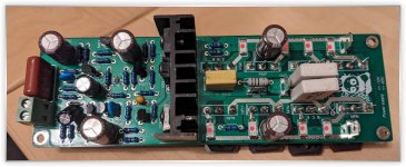
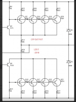
Those are resistors to ensure current sharing between the parallel outputs. They are installed upside down for some reason. I think they are 50 mOhm or 0.050 Ohm each.
Those are resistors to ensure current sharing between the parallel outputs. They are installed upside down for some reason. I think they are 50 mOhm or 0.050 Ohm each.
awesome, had a suspicion and was gonna get it off the board tonight after work, thanks for confirming
So I did a lot more work and I have found that I get better THD with genuine Toshiba 2SC5171/2SA1930 drivers and with Toshiba (Japan) O gain rank 2SC5200 and 2SA1943. (The THD is almost half what I measured with genuine ON Semi NJW0302G and NJW0281G even with genuine Toshiba 2SC5171/2SA1930 drivers from the same batch. I was not expecting that.) The large case Toshiba outputs are hard to fit and I can not install the two screws at the output end of the PCB.
I obtained the genuine Toshiba 2SC5171/2SA1930 drivers by disassembling the left and right channels of an old amp. So both are the same batch and both are genuine.
The attached results are the best that I can achieve at 64W output with the L20.5. These results are similar to what I achieved with the L20 V7 DIY kit (CFP version) which was older and still came with Toshiba 2SC5171/2SA1930 drivers. The L20 V7 was bought a number of years ago now.
I suggest that other L20.5 users get rid of the D1047 B817 outputs (which burn up in my experience) and replace the downgrade drivers with genuine Toshiba. That way you can get the expected low THD performance.
With the +/-56V supplies (112V rail to rail) and 4 Ohm load this 64W test (4 Amps) is fairly hard on the amplifier considering how small the official LJM L20.5 heatsinks are. They get very hot during the test. With the L20.5 surviving my tests (with genuine Toshiba outputs and drivers) I am now hopeful it will also be reliable.
yeah, see thats the issue, where can you even find reliable 2SC5171/2SA1930 drivers, practically impossible. there are some ebay sellers in the USA, but who knows where they even got them
i have an older sony avr i can dig through to see whats in there i suppose
leading me to my next question, if anyones tried the MJE15030 / MJE15031
Ah, yes, these two should have been 2SA1930 & 2SC5171, but he has silently "upgraded" them with inferrior KTC4370/KTA1659. Initially, I have purchased the adequate Inchange 2SA1930 & 2SC5171 pair. Now I have decided to replace them too with adequate ON-Semi MJE1530 / MJE1531. If you do the same, dont forget to isolate them with mica tabs from the heat sink.
By the way, I have found even better alternative for output pairs: NJW3281G / NJW1302G which have symmetrical characteristics in complementary configuration. I already have replacements for small input transistors (I did that already), so I need only an idea what to do with 2SD669. I already have an Inchange version but I want to make ON-Semi only amplifier to make sure noting interesting happens in the near future. For the sake of safety and peace of minds.
Regards.

have you had a chance to try the MJE15030 / MJE15031 yet?
i've got a smoked board and dont feel like buying another junk board from china
most if not all of the parts that are toast on my board can all be replaced from digi-key (however the 15030 would have to come from NTE, not OnSemi with digikey due to stock at this time)
the entire input side measured just fine, so just the main transistors, the driver transistors, and plan to upgrade the 5 larger caps across the board
just need the final puzzle piece of which driver transistors to use
i've also built a digi-key list that has every replacement part, but i'm not sure if i can share it publicly? digikeys dotcom website slash 'en/mylists/list/W2TASEXBAI' you for sure have to have an account at digikey, so give it a shot and see if it loads up. only missing a few key parts at this time (2 caps: 16v 470uF, 50v 10uF, the zdiode, the driver transistors once i decide on which to use, and the h669a)
Last edited:
hey all, just wanted to give you a heads up, udailey, diyldr@gmail.com has hundreds of the 2SC5171 2SA1930 available. looks like a post from a bit ago shows him having bought up a huge order from digikey when they were going to be discontinued. he's sending me a few of them as we speak
so if you need to update/upgrade your driver trannies to the actual spec of 20.5, hit him up
Hi there, what power should the 50 mOhm resistors 8R22/R30/R31/R33 ] have ? Is 2 watts enough or does it have to be more resilient?
edit: "Ok now I turned my brain on: with a collector current of 2 A and 50 mOhm, it is probably only 100 mWatt"

edit: "Ok now I turned my brain on: with a collector current of 2 A and 50 mOhm, it is probably only 100 mWatt"
Last edited:
2W is ok. Parallel equivalent of four is 0.0125 Ohm. In parallel each set of four 2W can handle 8W.
The 8W 0.0125 Ohm equivalent has plenty of margin compared to the 0.1 Ohm 5W (R20).
The 8W 0.0125 Ohm equivalent has plenty of margin compared to the 0.1 Ohm 5W (R20).
hey all, so i sourced all my parts (well i did a while ago) and am just getting all the nonsense desoldered (painstaking process)
i plan to replace all the caps except for the one nichicon cap already on the board (16v470uf), the R05 resistors, i found genuine thoshiba 5171/1930s from another board member (mentioned in post above), and got genuine toshiba 5200/1943s from digikey
however now i'm reading about transistor matching, which i know absolutely nothing about. i only ordered 5 pairs of the 5171/1930 (need 2 pair), and only 10 pairs of the 5200/1943 (need 8 pair), so i dont exactly have much wiggle room
how critical to this build is that going to be? i'm certain the board i originally ordered from china wasn't matched, so i wasn't expecting that level of performance. the THD on this thing is already well in the range of acceptable, so i dont need to go spec chasing. so would i even need to bother? or is this one of those things that 'only shows up in a spec sheet' type mod/considerations
if yes, it's critical to the build and not 'well it makes it slightly better', then which ones am i matching below? Q2 to Q10, 14 and 17...etc? Or Q2, 14, 18....to one another? and specifically what am i matching, and how would i go about it cheaply as i'm not planning on ever doing this again, i've seen the DROK testor and atlas DCA55, but do those measure what i'm suppose to be matching on?
thanks all
Attachments
The single batches of genuine Toshiba 5200 and 1943 that I have bought from Mouser or Digikey were very consistent.
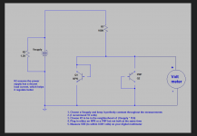
I suggest that you measure and write down (neatly) the Vbe and gain of each transistor. (Perhaps with a fine sharpie marker on the back of the heat spreader.)
Then sort them in order and post a photograph. You might fine that the genuine Toshiba are quite consistent within one batch.
Perhaps 100mA or 1A are good test currents. (Perhaps 5V Vce or 10V Vce, with a heatsink.) What test setup do you have for this?
does the attached circuit look like a valid one to use for capturing the Vbe?The single batches of genuine Toshiba 5200 and 1943 that I have bought from Mouser or Digikey were very consistent.
I suggest that you measure and write down (neatly) the Vbe and gain of each transistor. (Perhaps with a fine sharpie marker on the back of the heat spreader.)
Then sort them in order and post a photograph. You might fine that the genuine Toshiba are quite consistent within one batch.
Perhaps 100mA or 1A are good test currents. (Perhaps 5V Vce or 10V Vce, with a heatsink.) What test setup do you have for this?
Attachments
- Home
- Amplifiers
- Solid State
- L20.5 AP SYS Test data My design