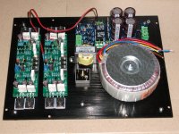
I also finished mine last week – see photos below. As the supplier told me that heat sink is optional, I only ordered 2 amp boards plus 1 power supply board (with speaker protector and soft start).
The transformer is an RS 225VA 25Vx2.
Power consumption measured at power socket is approx. 10W. The case is ice cool at normal listening level and therefore I am planning to block the venting holes to prevent dust from going in.
DC measured at speaker out:
Right Channel: 14.3mv
Left Channel: 10.0mv
Attachments
Last edited:
So what is your heatsink, maxilogic, just the sheet metal base? Whether your normal level is very low or not or whatever the efficiency of your speakers, just be careful not to turn up the volume or short the outputs as you have no overload protection yet, either.
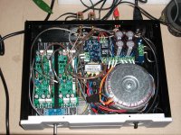
With the power and signal circuits close together like that, I think you will have some noise and sound quality problems there. I would reconsider that layout.
With the power and signal circuits close together like that, I think you will have some noise and sound quality problems there. I would reconsider that layout.
Last edited:
So what is your heatsink, maxilogic, just the sheet metal base? Whether your normal level is very low or not or whatever the efficiency of your speakers, just be careful not to turn up the volume or short the outputs as you have no overload protection yet, either.
With the power and signal circuits close together like that, I think you will have some noise and sound quality problems there. I would reconsider that layout.
Thanks for the reminder. It is connected to a pair of Usher S-520 (86db, 8 ohms, 50W). The volume is low as we all live in a very small apartment here in Hong Kong (except for those super rich of course). By the way, the whole chassis is made of aluminum and the base is 4mm thick. I am using a watt meter to monitor the power consumption. Even I turn the volume up a bit above my normal listening level, the max. is only 14W.
With regard to noise, the input signal cable is shielded all the way from RCA to the amp board. I can't hear any noise from 0 volume (7 0'clock position) to 10 or 11 O'clock.
Anyway, I have changed my mind not to block the venting holes as it could be problem in summer.
Hi,
Maxilogic and Activexp, it looks great! Can you tell us what kind of pre amp are you applying?
I have a TDA7294 based amplifier hooked to a DAC, but I have to use an equalizer to adapt the sound to my liking. I'm really thinking about swapping the TDA7294 board for this L12-2.
thanks!
Maxilogic and Activexp, it looks great! Can you tell us what kind of pre amp are you applying?
I have a TDA7294 based amplifier hooked to a DAC, but I have to use an equalizer to adapt the sound to my liking. I'm really thinking about swapping the TDA7294 board for this L12-2.
thanks!
Hi,
Maxilogic and Activexp, it looks great! Can you tell us what kind of pre amp are you applying?
I have a TDA7294 based amplifier hooked to a DAC, but I have to use an equalizer to adapt the sound to my liking. I'm really thinking about swapping the TDA7294 board for this L12-2.
thanks!
I'm using a PGA2311 based pre-amp board like this one on ebay
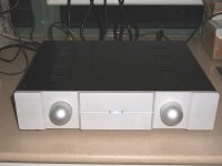
I also invested in a nice case for it 😀

Hi,
Maxilogic and Activexp, it looks great! Can you tell us what kind of pre amp are you applying?
I have a TDA7294 based amplifier hooked to a DAC, but I have to use an equalizer to adapt the sound to my liking. I'm really thinking about swapping the TDA7294 board for this L12-2.
thanks!
Mine is directly connected to a 1974 DAC. No preamp or buffer.
Hi,
Thanks a lot for the informations.
I have a toroidal transformer 225VA; 25V; 25V, but some technical information refer that the suitable power supply is +-50V or 30 - 50V. What do think about this? Can we expect less quality sound or other issues?
Thanks!
Thanks a lot for the informations.
I have a toroidal transformer 225VA; 25V; 25V, but some technical information refer that the suitable power supply is +-50V or 30 - 50V. What do think about this? Can we expect less quality sound or other issues?
Thanks!
Hi,
your trafo will provide approximately + and -35V dc. So within the advised range. The power rating of the trafo seems ok to me.
your trafo will provide approximately + and -35V dc. So within the advised range. The power rating of the trafo seems ok to me.
Ah....slight (ahem) error. It's actually L12-2 model. Here's my ref: 400528793711 There are others though.
.
There are some pictures on Ebay that show boards with different references for output transistors: C2837 9D Y + A1186 9D Y or C2837 97 Y + A1186 93 Y ... etc.
Thanks for your advices.
Those are manufacturing lot numbers codes you are concerned about there.
The part no. is 2SC2837 etc. followed on the line below by a 2 character lot
number code plus an optional Hfe range code letter.
Download the Sanken datasheet for an illustration where they should be located.
2SC2837 Datasheet pdf - Silicon NPN Transistor - Sanken
The part no. is 2SC2837 etc. followed on the line below by a 2 character lot
number code plus an optional Hfe range code letter.
Download the Sanken datasheet for an illustration where they should be located.
2SC2837 Datasheet pdf - Silicon NPN Transistor - Sanken
I have a suggestion. Regarding L12-2.
With scissors, cut off the capacitance. Its model for 101.
L12-2 will behave better.
In addition.
Questions about the static current.
Because CFP output make the distortion of the voltage range. Are lower than those of ordinary amplifier.
So. More static current does not have a better performance.
10-20 ma. Is the ideal, the minimum distortion performance. Because of the existence of switch distortion.
Attachments
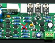
As a result of the existence of CFP switch distortion.
So we choose high-frequency transistors as much as possible. Reduce switch distortion.
Why I choose 2 sa1186, 2 sc2837.
Because it's not much of a linear gain. So the 2 on the tube.
So we choose high-frequency transistors as much as possible. Reduce switch distortion.
Why I choose 2 sa1186, 2 sc2837.
Because it's not much of a linear gain. So the 2 on the tube.
Interesting. So you recommend removing the components used for frequency compensation?I have a suggestion. Regarding L12-2.
With scissors, cut off the capacitance. Its model for 101.
L12-2 will behave better......
Was there really much problem with the stability of Rev. 2?
Interesting. So you recommend removing the components used for frequency compensation?
Was there really much problem with the stability of Rev. 2?
This is not the frequency compensation. This is just a filter.
The high frequency sound better.
Thank you for the explanation, LJM......This is just a filter. The high frequency sound better.
Your published schematic for L12-2 (post #5) shows both standard Miller Compensation (C11) and what is sometimes called phase lag-lead compensation (C14, R30). I asked because I have seen this RC shunt arrangement across the LTP used as the frequency compensation in an audio amplifier. I assume this is the filter you refer to?
Hi,
simmed the L12-2 with different compensations.
A bit suprprisingly, but the lead-lag network Network R30/C14 seems to not affect the OL-gain response.
It should raise the OL gain above a certain breakpoint frequency.
Seems that the Miller Cap C11 swaps any other influence.
See attached pdfs.
In any case offers the amp plenty of phase-reserve at A=0dB, which explains the stability when driving large capacitive loads like my Electrostats.
A interesting twist might be a Two-pole-Miller compensation and/or to connect the Miller cap to the collector of Q6 instead of the base of Q12.
A twist discussed in the AES Paper "Analysis of Two-Pole Compensation in Linear Audio Amplifiers", H. Dymond, Phil Mellor, 129th AES, 4-7 Nov. 2010.
jauu
Calvin
ps. As I had no model for the output transistors I chose the similar 2SA1216/2SC2922 instead, which are of the same fast ring-emitter types as the 2SA1186/2SC2837 and same manufacturer, i.e. Sanken
Attachments
-
L12-2 Poweramp - OL-gain wo C11 and R30_C14.pdf265.6 KB · Views: 515
-
L12-2 Poweramp - OL-gain wo R30_C14.pdf273.1 KB · Views: 419
-
L12-2 Poweramp - OL-gain original .pdf273.1 KB · Views: 441
-
L12-2 Poweramp - OL-gain schem and values.pdf38.3 KB · Views: 566
-
L12-2 Poweramp - CL-gain schem and values.pdf38.4 KB · Views: 681
-
L12-2 Poweramp - OL-gain wo C11.pdf265.3 KB · Views: 432
Last edited:
Hi,
did some more compensation sims, all with R30/C14 omitted.
First file is a sim of stability (after the AES paper) with Miller-Compensation C11=100p (wo. R30/C14).
The simulator frequency response calculates small signal behaviour.
The pulsed signal shows large signal begahaviour more realistic.
Therefore a 1kHz-sine input signal large enough to drive the amp close to clipping is topped with a rectangular pulse of 1/10 the amplitude and 10x the frequency of the sine.
Signals are taken from the input, V(out) and the output point "o" right before the output filter where the feedback trace connects (with offsets for ease of recognition).
Any sign of ringing on the pulse edges of the Signal indicates instability.
The sim here shows clean pulses, hence high stability.
The second file shows a reduced schematic with 3-Pole-Miller-Compensation.
It adds 2 caps and a resistor.
It differs to the classic compensation that connected C17 to the Base of Q12 and C18 to the negative supply line.
Instead C17 is connected to the collector of the Input transistor Q6 and C18 is connected to signal gnd.
The connection of C17 to the collector of Q6 improves the PSRR.
Positive and negative PSRR differ alot if C18 is connected as usual to the negative supply.
Choosing signal gnd as connection instead improves the negative PSRR considerably wo. affecting the postive PSRR.
The OpenLoop-sim shows a much increased and more constant OL-gain-level over the audio band and a steeper drop >10kHz.
Also the Unity-gain-OL-frequency rose from 418kHz to 890kHz.
The phase reserve dropped from ~82° to still sufficiently high 66°.
The stability sim shows no ringing, indicating high stability.
The last six files show the sims of pos and neg PSRR for Miller-compensation, the classical 3-pole-Miller-compensation and the 3-pole-Miller-compensation after the above schematic.
jauu
Calvin
Attachments
-
L12-2 Poweramp - Miller comp - stability test.pdf70.4 KB · Views: 335
-
L12-2 Poweramp - 3-pole-Miller-comp - schematic.pdf12.3 KB · Views: 364
-
L12-2 Poweramp - OL-gain 3-pole-Miller-comp.pdf285.1 KB · Views: 245
-
L12-2 Poweramp - 3-pole-Miller-comp - stability test.pdf71.6 KB · Views: 224
-
L12-2 Poweramp - Miller-comp - pos PSRR.pdf159.9 KB · Views: 293
-
L12-2 Poweramp - Miller-comp - neg PSRR.pdf153.3 KB · Views: 257
-
L12-2 Poweramp - classic 3-pole-Miller-comp - pos PSRR.pdf160.7 KB · Views: 302
-
L12-2 Poweramp - classic 3-pole-Miller-comp - neg PSRR.pdf160 KB · Views: 257
-
L12-2 Poweramp - 3-pole-Miller-comp - pos PSRR.pdf159.4 KB · Views: 228
-
L12-2 Poweramp - 3-pole-Miller-comp - neg PSRR.pdf156.9 KB · Views: 273
Thanks for your interesting work there, Calvin. I've not yet encountered 3-pole compensation schemes in audio amplifiers. It's interesting from an experimental point of view but would you anticipate better or rather, more worthwhile, practical results than with other, better known and currently discussed compensations like 2-pole, TMC, IIC, OIC etc?
- Home
- Amplifiers
- Solid State
- L12-2 CFP Output amp 120W*2 8R