ok guys, sorry, I didn't want to impose.
I'm not yet used to the "good use" of the forum.
I'll be more carefull in the futur
best regards
I'm not yet used to the "good use" of the forum.
I'll be more carefull in the futur
best regards
it is a cfp output .so , it is not have The distortion.
In a very small static current IQ.
It will be very low distortion.
In a very small static current IQ.
It will be very low distortion.
it is a cfp output .so , it is not have The distortion.
In a very small static current IQ.
It will be very low distortion.
Has this topology any advantage of crossover distortion behavior over traditional class-AB designs? I read somewhere here mentioning that bias current value will not affect on performance at all. Is this true?
I think he was talking about a range of bias current over which it is not critical.
In the assembly instructions, it was specified as 10-20 mA per pair or 20-40 mA total.
The theoretical bias for CFP pairs is much less than EF designs and is said to be
13 mA/pair at some standard temperature, so it seems fine.
Take a look at the specs. of Self's Load - Invariant amplifier. The schematic is in several of his
books and articles. It is a blameless format design but has 2 prs CFP output stage, like this L12.
Has this topology any advantage of crossover distortion behavior over traditional class-AB designs? I read somewhere here mentioning that bias current value will not affect on performance at all. Is this true?
right
,because CFP OUTPUT,Hand in the distortion zone + -0.6V。
2 Level EF OUTPUT distortion zone + -1.2V
so CFP Can be smaller bias current value
CFP Drive transistor In conduction forever。So it does not need to work on CLASS A.
Attachments
Last edited:
Hi,
Starting to connect the several modules, I have the following doubt: the power supply have +VCC, GND and -VCC. The amplifier boards have VCC, GND , VEE. So, please confirm that the right connection is:
(+VCC power supply -> VCC amp)
(GND -> GND)
(-VCC power supply-> VEE).
Thanks a lot!
Starting to connect the several modules, I have the following doubt: the power supply have +VCC, GND and -VCC. The amplifier boards have VCC, GND , VEE. So, please confirm that the right connection is:
(+VCC power supply -> VCC amp)
(GND -> GND)
(-VCC power supply-> VEE).
Thanks a lot!
Hi,
Starting to connect the several modules, I have the following doubt: the power supply have +VCC, GND and -VCC. The amplifier boards have VCC, GND , VEE. So, please confirm that the right connection is:
(+VCC power supply -> VCC amp)
(GND -> GND)
(-VCC power supply-> VEE).
Thanks a lot!
Yes you are correct. If you look closely at the board you will see that it is marked VCC + and VEE -.
Cheers 🙂
Dear LJM, have you tested improvements in VAS?
I've always had doubts. What produces better sound? a transistor in cascodo mode or one transistor in darlington mode. See schematics images, figure C or D.
If anyone has tried this also, could tell his experience?.
When I mean better sound, I think it is very important slew-rate, distortion and linearity.
Thank you very much.
An externally hosted image should be here but it was not working when we last tested it.
If you wish to use a cascoded VAS, higher rail voltage is required for the same output drive. It requires a more complex (read "expensive") design with more rail voltages.
This is probably off-topic in a thread about an established commercial module/kit product, so it may be better to start a new topic or post your general question in one about VAS designs.
This is probably off-topic in a thread about an established commercial module/kit product, so it may be better to start a new topic or post your general question in one about VAS designs.
If you wish to use a cascoded VAS, higher rail voltage is required for the same output drive. It requires a more complex (read "expensive") design with more rail voltages.
This is probably off-topic in a thread about an established commercial module/kit product, so it may be better to start a new topic or post your general question in one about VAS designs.
OK, you're right.
I wanted to know if Mr. LJM had experienced this with your module L12.
I will look for an existing thread and I will expose my questions VAS.
Thank you.
looking for advises
Hello folks, I'm still playing with my L12-2 modules and read the other day that they Can direct drive 32 ohm headphones load Funny things, my cans are 32ohm ones.
Any suggestions about how to connect things nicely?
Eliot sound products advises an adaptor circuit in order to adapt again and impedance,(http://sound.westhost.com/project100.htm) but whats to point if the impedance is already fine? Maybe a resistor to limit the output?
I'm searching the web for more infos or how to's.
From reading the shematics of the L12-2 power amp, I was trying to decipher what was exactly the audio signal path and then that components it goes througt (resistor caps) ,appart from the path used by the power supply output?
And in the end, what's the true diagram of the power board
this one

, or that one?
Any help or advise is welcome.
best regards.
Hello folks, I'm still playing with my L12-2 modules and read the other day that they Can direct drive 32 ohm headphones load Funny things, my cans are 32ohm ones.
Any suggestions about how to connect things nicely?
Eliot sound products advises an adaptor circuit in order to adapt again and impedance,(http://sound.westhost.com/project100.htm) but whats to point if the impedance is already fine? Maybe a resistor to limit the output?
I'm searching the web for more infos or how to's.
From reading the shematics of the L12-2 power amp, I was trying to decipher what was exactly the audio signal path and then that components it goes througt (resistor caps) ,appart from the path used by the power supply output?
And in the end, what's the true diagram of the power board
this one
, or that one?
Any help or advise is welcome.
best regards.
Last edited:
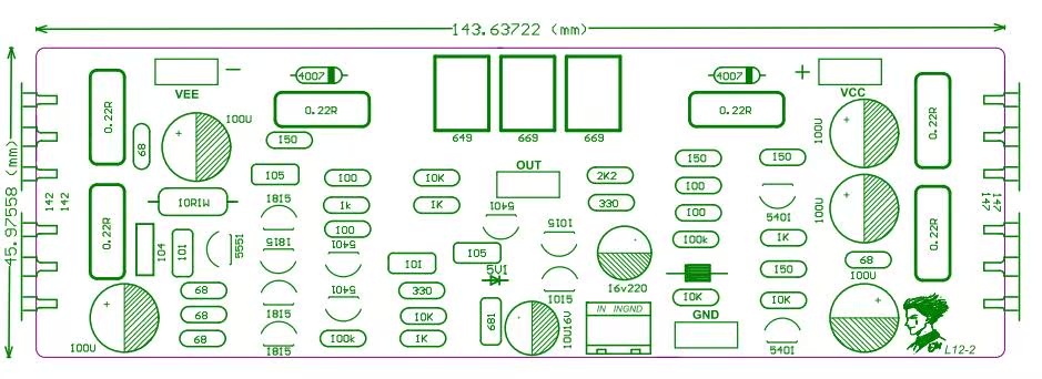
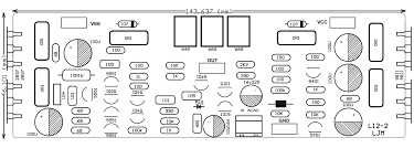
I think these are all LJM L12-2 Boards, just a matter of version/batch. Mine is the second one, without model number and logo. I ordered it directly from LJM a few months back. The other 2 versions are shown on his Chinese online store.
This is the parts layout diagram and all the diagrams are the same. Can you point out anything apart from the logo and colour that is different? The schematic is shown and discussed earlier in the thread if you care to read it.
If you are considering headphone amplifiers which only need milliwatts of output, it seems unnecessary to use an amplifier designed for more than 120W/8R and almost 200W/4R. Perhaps if you make a mistake with your connections you will not just ruin your headphones but completely destroy them.
You certainly can plug headphones into any power amplifier and almost any headphones will work because solid-state amplifiers have almost zero output impedance. Any impedance load above 4R can be driven at full rated power but it is safer to either adapt headphones via something like ESP's recommendation or use a purpose-built headphone amplifier that is limited in how much power it can deliver and likely a lot quieter and better sounding too, as it does not have to maintain high voltage rails and the potential to drive high power.
Headphone amplifiers are optimized for very low output voltage which is best delivered in small class A amplifiers. Otherwise, crossover distortion also becomes a problem.
Personally, I think it's a bad idea driving headphones with the full potential to drive large loudspeakers at high SPL. It's not optimal and a waste of space when you can have much better performance with the right size amplification. Check out what others think on our Headphones Systems forum.
Last edited:
I am using a 25v-0-25v transformer for this amp. What if I change the transformer to 35v-0-35v or 40v-0-40v? Should I expect any improvement in audio quality (not power)?
Please comment.
Please comment.
It is LJM's thread to answer you but 50V is the recommended maximum supply voltage and just permits 120W, if the transformer is large and the supply does not sag below this voltage.I am using a 25v-0-25v transformer for this amp. What if I change the transformer to 35v-0-35v or 40v-0-40v? Should I expect any improvement in audio quality (not power)?...
The amplifier will work fine and is specified for 35 AC windings giving 50V. You are also fine with 25V AC windings giving 36 VDC rails though there is a corresponding loss of power with 8R loads while there is still plenty with 4-6R loads. Obviously, voltage is only half the requirement - you need enough current for 2 amplifiers producing 120W output into 8R loads and ~180W into 4R with around 70% efficiency. Your 2 x 35VAC transformer will need to supply 320W continuous and to maintain regulation, it would need to be be 500VA rated. The lower rated 35VAC transformer could be 300VA.
I don't believe that using 40VAC windings for 57 VDC rails is a good idea unless you have larger heatsinks and protect the output stage with current/voltage limiting. It is not considered possible to add more output transistors to CFP designs because of instability so I think it is wise to leave it as is and stay within recommended limits. 🙂
Last edited:
I guess I should have answered the question too. 😱.
I don't think that lowering supply rails by 30% to 36V will have a significant affect on the sound quality. I mean here, the identifiable elements of "sound quality" that arise from crossover and other distortions mixed with small amounts of noise that are inevitable in typical solid state amplifiers.
I don't think that lowering supply rails by 30% to 36V will have a significant affect on the sound quality. I mean here, the identifiable elements of "sound quality" that arise from crossover and other distortions mixed with small amounts of noise that are inevitable in typical solid state amplifiers.
Hi,
lowering the supply voltages...
Been there done that, no prob at all.
Raising the transformer voltages is ok also, as long as the limits of the amp are not exceeded.
In the case of the LM12-2 its the breakdown voltage of the four lytics C1,2,12,13 that define the upper dc-voltage limit to +-63V.
As there´s always a chance of overvoltage and/or spikes on the main power line one should have a reserve of ~10%.
In our case, +-56V (amplifier idling) would be a sane upper limit.
If You don´t trust the chinese parts, especially the specs of the four Lytics w.r.t originality, stay lower.
LJMs recommendation for ~+-50V (36Vac) is sensible and safe.
It for sure isn´t a good idea to squeeze the last Watt out of this design or any other amp-design.
If ou want more power, think about possibly bridging two modules, or look for a different module in first place.
jauu
Calvin
Ok,
I've been thinking about using those modules in a bi amplification project with Ob speakers.
but I need a couple of advise of more experienced user.
one module, handeling mids and high (300hz and up) would drive a PS220-8 8" Point Source Full-Range Neo Driver from dayton. rating at 95.6 dB @ 1W/1m and with a power handeling of 40watt RMS , 80watt max,I guess that I'd better "calm down" a module but I'm not sure if the trimming mod advised by calvin would be sufficient and wondering If I could go futher down without a loss of sonic's quality.
the other module would driver a pair of eminence alpha15a. rated 97dB @ 1W/1m with 8ohm load and with a power handeling of 200Watt RMS (400 max)
If a do the math because of the parallel connection, it becomes a 4ohm load with a power handeling of 400watt rms and a sensitivity of 97+6db = 103db.
If those modules outputs 180watt or even 150-120watt after the trimmed down mod it still seems like a good amount of watt in a 103db pair of speakers isn't it?
I also thought about using ljm L25D amp modules as I was advised that the IRS2092 chip would be great for handeling the bass duty and seems more designed with the 4ohm handeling job in mind. with an output of 250w in 4ohms load and speakers of 103db I might expect evenbetter grip/authority in the bass....but maybe it would be also overkill.
It's just speculation, I miss field practice.
Any advise is welcome.
Best regards to all.
Dookie182
Hi,
80W@8Ohm translates to 25Vrms, hence 36Vpeak.
Plus ~4V Saturation overhead (Clipping-Limit) that the Amp requires and You end up at supply rail values of +-40V.
A transformer with +-30V will suffice.
As long as the amp doesn´t clip a higher wattage specced amp than the speaker´s wattage is no real harm for the speaker.
The same supply rail value would result in 160W into 4Ohms (in practise probabely rather 140W).
The current required is 6Arms/8.5Apeak.
This is close to the amp´s transistor limit 8for two of the four output transistors) and as the amp has no protection at all against overcurrent, You´d be very close to breakdown.
There are two measurements that I would take into account.
The first is to use two amp-modules in bridged mode for each bass and
the second is to reduce the supply lines.
A transformer with +-24V will give ~+-32V rails.
Subtracting 4V for saturation we have +-28V or 20Vrms.
This gives 50W@8Ohms and 100W @4Ohm and in bridged mode ~150W @8Ohms and ~300W @4Ohms.
This power is fully ok to serve the Fullranger with a single amp-module and more than enough in bridged mode to drive a bass and staying on the safe side of the amp.
One big advantage of this kind of configuration is, that only one power suply is needed as all amps could be supplied from the same +-24V Transformer.
Also all amp modules have the same gain and sonic fingerprint.
Regarding the low cost of the amp modules I think it´s worth considering this concept.
If You want to supply with (two) SMPS the SMPSs should have an output voltage between 32V and max. 36V (36V is quite standard).
jauu
Calvin
- Home
- Amplifiers
- Solid State
- L12-2 CFP Output amp 120W*2 8R