C5 is the dc blocking capacitor on the input right?? which is missing on version 4.2Hello LimOnade,
Here are pictures of the PCB with the references (I have done to understand the schematic) and the schematic of version 4 (given by Calvin). References are the same on both. On the schematics polarity of C12 and C13 must be inverted, R2 is 150 Ohms, C6 and C4 are in fact 1µf. It seems that your version have not the same references for Q11, Q13, Q17 and Q19 (2SC1815). Also, R16 is replaced by a capacitor, R7 and Q1 are inverted, C5 is missing. Good luck
One "Mod" was using a groundlift resistor 10 Ohm at the rca input, at the shielding. Second was to use a Boucherot Network 10ohm 5W and a 1 µH coil at the output.
Perhaps you can try to use only one connection from your starpoint to the protection board. As i know ground is bridged on the protection board...
I think the hum has not only the reason in a missing input capacitor...
Peter
Perhaps you can try to use only one connection from your starpoint to the protection board. As i know ground is bridged on the protection board...
I think the hum has not only the reason in a missing input capacitor...
Peter
Last edited:
Hi,
I assume that you built the amp with a metal casing connected to PE?
As you wrote the problem seems to be the line-signal/RCA wiring.
Hum can occur here if the RCAs are not insulated to the casing.
I had cases where a ´insulated´ RCA still made contact to the casing, due to screwing it in too hard, resp. the low quality of the soft insulation material.
You may also test to connect both gnd-lugs of the RCA together with a thick wire and going from this single point to the lownoise point powersupply joint.
Also add a 10nF cap from the RCA lug immideately to the casing/PE.
You don´t need to connect coaxial cables from RCAs to amp´s inputs ... at least dont connect the screens at the amp sides, just the signals.
jauu
Calvin
One "Mod" was using a groundlift resistor 10 Ohm at the rca input, at the shielding. Second was to use a Boucherot Network 10ohm 5W and a 1 µH coil at the output.
Perhaps you can try to use only one connection from your starpoint to the protection board. As i know ground is bridged on the protection board...
I think the hum has not only the reason in a missing input capacitor...
Peter
Thanks Peter, it gave me food for though so I tried the following with no effect to hum. It's still there..
- Disconnected the signal shields (ground) from amps
- connected new ground wires from the PSU and connected them to each RCA plug

Hi,
I assume that you built the amp with a metal casing connected to PE?
As you wrote the problem seems to be the line-signal/RCA wiring.
Hum can occur here if the RCAs are not insulated to the casing.
I had cases where a ´insulated´ RCA still made contact to the casing, due to screwing it in too hard, resp. the low quality of the soft insulation material.
You may also test to connect both gnd-lugs of the RCA together with a thick wire and going from this single point to the lownoise point powersupply joint.
Also add a 10nF cap from the RCA lug immideately to the casing/PE.
You don´t need to connect coaxial cables from RCAs to amp´s inputs ... at least dont connect the screens at the amp sides, just the signals.
jauu
Calvin
Hi Calvin,
My back panel to the amp is plywood, so there should be no accidental connection to chassis. I tried your suggestion above and ran a ground straight from RCA plug to PSU. Disconnected the shield from both amp signal inputs. Sadly no difference.
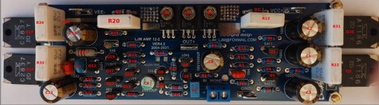
Finished tracing out the Ver4.2 pcb and Ive attached an annotated picture of the pcb showing the part numbers according to post #383. I've also attached a parts list corresponding to the picture. Schematic to follow.
Attachments
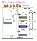
My friend Ron has almost exactly the same system as you, with, in the past similar issues. His answer and suggestion are as follows, good luck. Great graphics by the way. I'm tempted to steal them for a forthcoming video I'm making on this very subject. lol.
I added the resistor between the star ground point at the large PSU filter capacitors and the chassis.
It would probably be best to add one between the rectifier/filter board output common point and the chassis.
For a value, I would suggest starting with perhaps a 4.7K ohm 1/4 watt resistor and adjust from there.
It is best NOT to simply short that to the chassis because then if there are any ground potential offsets in the signal source, large currents could be generated in the common ground connections between source and amplifier.
Michael Beeny
@michael beeny you are welcome to steal away the graphics sir. Happy to send you the master file so you can modify to suit your needs.
My chassis is a wooden box, so I done have anything connected to mains earth as yet.
My chassis is a wooden box, so I done have anything connected to mains earth as yet.
As a PS on the L12/2 v5. Here in New Zealand, it is impossible to obtain the recommended transistors that are suggested by LJM. They are either unlisted or classed as obsolete. Why use such transistors in the first place?
Hi dakku. I was not expecting the wooden box chassis lol. You can still use the same mod. Connect the star earth point to the supply plug earth via the resistor rather than directly. Odd buzzes and hum can really be a pig to sort out. In your case it has to be a loop of some kind. The combo you have should be dead quiet.
@michael beeny I am tempted to just buy a 2nd rectifier board and run the two boards from one torodial transformer.
Do you think that should take care of ground issues?
Do you think that should take care of ground issues?
It might. To be honest, it's not a problem I haven't been able to fix in the past. Looking at the positive side, it will, on paper give each channel a higher peak power output, as you will get less voltage drop on the DC side. Something I'm thinking about in my latest amplifier project on my channel.
@dakku
In your schematics you don't draw signal grounds, which are essential to spot the real source of your problem. Just draw the signal grounds and you'll see a huge ground loop that you have created. You should connect your both signal grounds at a single point. I bet you have connected left channels' ground to the left channel board and right channels' signal ground to the right channel board. That is wrong: either-or, not both. Go back to the @digi01 post #7 and try to learn.

In your schematics you don't draw signal grounds, which are essential to spot the real source of your problem. Just draw the signal grounds and you'll see a huge ground loop that you have created. You should connect your both signal grounds at a single point. I bet you have connected left channels' ground to the left channel board and right channels' signal ground to the right channel board. That is wrong: either-or, not both. Go back to the @digi01 post #7 and try to learn.
Attachments
Last edited:
@Berlusconi thank you sir. I had a read though the entire 32page thread but ended up rather confused. Will try to read through again and compare diagrams.
In the meantime this is how my RCA signal wires are connected. RCA signal and shield are connected to each amp respectively.
Would be grateful if you can help outline the potential ground loop.

In the meantime this is how my RCA signal wires are connected. RCA signal and shield are connected to each amp respectively.
Would be grateful if you can help outline the potential ground loop.
HUH, pure waste of time. Just @digi01 posts are relevant.Will try to read through again and compare
ALL other posts of that thread is ordinary bulshit, Safety-Earth-Police yaddah-yaddah.
Let me explain you how to solve this problem.
Refer to the wiring diagram in my previous post #1.015
1. Your RCA connectors should be as close as possible to each other.
2. Solder the RCA grounds to each other with a short wire and use one wire to connect the RCA ground to the star ground
3. Connect just the signal of the RCAs to INs at the board and do not connect anything to the input GND on the board. Your input grounds are now connected to the star ground via one, single, wire. That is essential.
4. Connect grounds of the both channels to the star ground with a THICK wire to ensure the lowest possible resistance.
Thats all.
Hello all,
I have a little issue with my build 4.2 board.
No humm but a slight buzz from a spealker and when I play musique, I get a slight crakling, popping noise and distortion.
1 - I use a chinese SMPS, could the SMPS be the issue?
2 - I was thinking going for a toroid transformet with a rectifier board. Is 30VA enaught or should I go higher?
Thanks
Last edited:
I was thinking about this one 50VA 30V
https://fr.aliexpress.com/item/1005....0.0.25d4378dCVFXsX&mp=1&gatewayAdapt=glo2fra
https://fr.aliexpress.com/item/1005....0.0.25d4378dCVFXsX&mp=1&gatewayAdapt=glo2fra
- Home
- Amplifiers
- Solid State
- L12-2 CFP Output amp 120W*2 8R