😕.
What can I say. I spent hours on RS website for the L-Ad BOM and other projects and I could not find that size sink. Brilliant. Thankyou
They got a 4K/W taller one too: RS Stock No. 189-8151 Mfr. Part No. SK129-50,8-STS-220 Brand Fischer Elektronik
Stocked as SK129-50STS in TME
Stocked as SK129-50STS in TME
Salas, I see you did not attach your hot parts to heatsinks with insulators, what is the common practice on that regarding the risk of having a heatsink with voltage and the loss of heat conductivity? A very personal take on risk?
I wouldn't touch the board level sinks with a grounded cable or a probe or to a chassis associated with ground. Those instances would mean a hard short obviously.
When such actions to be avoided are under the original builder's control, a bit of thermal paste only and the simplified mounting are more practical for both work and rework, also more thermally efficient. If I was handing the build to unsuspecting persons I would insulate the semis on the board level sinks as a mishandling precaution.
For when outboard sinking to a heavy chassis or to external sinks in touch with a chassis, fully insulating the semis to the cooling surfaces is a MUST anyway.
P.S. The electrically floating board level sinks are discrete for each device in this design. That is why we could discuss choices in mounting practice. Insulation is a must for any devices sharing a common sink or chassis but working at different voltage levels in this or in other designs even when the sink or chassis is not grounded but floating.
As always the problem is between the device and the tools, tools don't jump, they're dropped... 😉
I just found 2pcs of 10,000uF/25V mundorf e-caps in the tool box!
Is the Voltage rated too low for L-adapter application?
It will be used to power my RPi3.
Don't want to waste them... 🙂
Is the Voltage rated too low for L-adapter application?
It will be used to power my RPi3.
Don't want to waste them... 🙂
I just found 2pcs of 10,000uF/25V mundorf e-caps in the tool box!
Is the Voltage rated too low for L-adapter application?
It will be used to power my RPi3.
Don't want to waste them... 🙂
Slurp, let me know your impressions using the L Adaptor on the RPi, I plan to do the same.
I am already powering my RPi3 with L-adapter.
I have tried both official pi Switching mode PS and 18650 battery;
Both lack energy and seem soft; although battery is a bit smoother and purer.
L adapter is absolutely amazing for digital use- more power and richer in every aspect.
I am still happy with LT1963 and LT3045 regs; but L-adapter is a very good upgrade.
I am already powering my RPi3 with L-adapter.
I have tried both official pi Switching mode PS and 18650 battery;
Both lack energy and seem soft; although battery is a bit smoother and purer.
L adapter is absolutely amazing for digital use- more power and richer in every aspect.
I am still happy with LT1963 and LT3045 regs; but L-adapter is a very good upgrade.
I did not intend it to also replace top rank LDO chip regs where they are still enough for power spec, intended it for higher power apps vs SMPS external units mainly, but its very good to hear from you that the L-Adapter can even pull such a subjective quality level trick.
I am using the LT3042 LDO right now. Can’t wait to do the same then. Thanks for the feedback.
Lets see if the so good subjective findings are consistent then.
Don't forget to factor in the output cables voltage drop on maximum load when setting the output. They better be substantially thick.
Salas, I hope you and our greek fellows are fine after the terrific storm.
BTW, about the quote and nano-computers à la Raspberry, any rule of thumb about wire gauge? These DIY micro-USB plug are tiny, I guess I can solder 20AWG on it but not more.
And I can't figure out if the use of a 5V and GND pin on the GPIO header is wise, I mean safe enough to bypass the micro-USB power socket and will bring any benefit.
The extra 0.1/0.2V is a handy trick, not curing the source of the problem sadly 🙂
Attachments
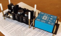
Hey, thanks. I have seen some use the GPIO header, I don't know how wise it may be. Dim Dim maybe knows better to answer if he will also read your question. On RPi 3 the red & black USB wire in the post#1's picture was enough at 5.1V L-A setting not to see the yellow thunderbolt popping up on Raspbian anymore. That one looked about 20AWG. Keep it as short as usable.
Oh yeah that bolt mystery... last question of the day, is a fuse on primary a good practice even if one on the secondary?
More LEDs better?
I can achieve 5.2v for Rpi with either 2 or 3 segments lit. I guess it is down to dissipation?
So does that mean it is 'better ' to go for 5.2v with 3 segments and not 2?
Talema 25va 7v tx
I can achieve 5.2v for Rpi with either 2 or 3 segments lit. I guess it is down to dissipation?
So does that mean it is 'better ' to go for 5.2v with 3 segments and not 2?
Talema 25va 7v tx
- Home
- Amplifiers
- Power Supplies
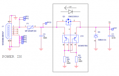
- L-Adapter