So I have my 2 boards built and tested and running nicely at 5.2v unloaded.
One powers the Pi and one powers the DAC board. Probably a little overkill amperage wise for the DAC but I am waiting on other components to build other psu for there.
I had a noise issue when I introduced the Isolator when powering with single 5v so I will try this later today and see how we get on.
I see you have used a dual 7V output transformer. Salas suggested we would need a 9V output transformer for 5V DC - any issues with the 7V output?
Erm....well spotted. I believe I have a blue talema 9v so maybe I picked up the wrong one. No issues so far.
What problem may occur if 'Q2 sees less than 2.5v' to quote the manual.? I guess an instability?
What problem may occur if 'Q2 sees less than 2.5v' to quote the manual.? I guess an instability?
is that ok that the reg consumes 33W 😕
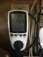
50VA trafo (14vac 3.57A), configured to 12vdc to feed Mytek Brooklyn Bridge. If internal switch power supply is used, it consumes less than 21W.
Turned the reg on just for a couple of minutes, otherwise the heatsink gets pretty hot, obviously bigger one should be used. Diodes are warm. 12vdc is stable.
Added data from Bridge manual.
Attachments

Last edited:
I see you have used a dual 7V output transformer. Salas suggested we would need a 9V output transformer for 5V DC - any issues with the 7V output?
He is not consuming as much current in his application yet. My Tx secondary suggestions are general for the DCin level to can cover even more ripple voltage losses for higher currents.
Erm....well spotted. I believe I have a blue talema 9v so maybe I picked up the wrong one. No issues so far.
What problem may occur if 'Q2 sees less than 2.5v' to quote the manual.? I guess an instability?
As long as the 2.5V criterion is met in your app you are good. If breached no oscillatory instability will occur, but the lower below that threshold you allow, a gradual loss of Vout voltage fix and worsening of all spec will happen until starving the Vref completely. Tell tale bad sign before even you measure that Vi-Vo is to see the Leds dimming a bit or blinking.
is that ok that the reg consumes 33W 😕
50VA trafo (14vac 3.57A), configured to 12vdc to feed Mytek Brooklyn Bridge. If internal switch power supply is used, it consumes less than 21W.
Turned the reg on just for a couple of minutes, otherwise the heatsink gets pretty hot, obviously bigger one should be used. Diodes are warm. 12vdc is stable.
Added data from Bridge manual.
Yes, the one in the picture is an obviously small sinking plate for your application. Enlarge it until adequate.
Part of the 33-21=12W difference in consumption from the wall should be the linear vs switching efficiency difference and another part a different power factor maybe. In general your build looks like behaving normally. Does your transformer become any warm as well? That should take some time in work to tell. Transformers lose about 40% of their nominal AC secondary current ability for DC in full bridge rectification.
@ dtses
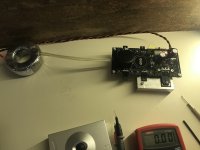
The probe modification in your first image 🙂
A bit of wire wrap and heat-shrink ? or is it something commercial ?
The probe modification in your first image 🙂
A bit of wire wrap and heat-shrink ? or is it something commercial ?
Yes, the one in the picture is an obviously small sinking plate for your application. Enlarge it until adequate.
Part of the 33-21=12W difference in consumption from the wall should be the linear vs switching efficiency difference and another part a different power factor maybe. In general your build looks like behaving normally. Does your transformer become any warm as well? That should take some time in work to tell. Transformers lose about 40% of their nominal AC secondary current ability for DC in full bridge rectification.
will find a bigger heatsink and check the toroid. As it is now, I did not notice any increase in temperature on it.
So all in all nothing to worry about? Should I maybe limit the current anyhow if that is possible with the reg? 🙂
@ dtses
The probe modification in your first image 🙂
A bit of wire wrap and heat-shrink ? or is it something commercial ?
just a tuned probe for ease of usage 🙂 these are needles, wrapped with wire and teflone tape over them + several heatshrinks.
these are needles, wrapped with wire and teflon tape over them + several heat-shrinks.
Sew clever ! 🙂
So all in all nothing to worry about? Should I maybe limit the current anyhow if that is possible with the reg? 🙂
No worries. Impossible, this PSU has no active current limiter. The load is its peak current arbiter. Up until the fuse and power parts refuse.
Is this a suitable transformer to use to power a RPi with DAC HAT (25VA, 8V AC secondary @ 3.2A) or would I be better finding a toroidal?
VPS16-1600 Triad Magnetics | Mouser United Kingdom
VPS16-1600 Triad Magnetics | Mouser United Kingdom
It will suffice with ease. Use parallel output mode connections as described in TRIAD's datasheet.
Sorry for all the questions!
Is this maybe a better choice of transformer than the one I posted previously - toroidal , dual 9V, 1.67A per output?
Is toroidal less likely to hum than an EI core and what are the advantages (or disadvantages) of using either an 8V, 9V or 10V secondary transformer for a 5V output?
Vigortronix VTX-146-030-109 Toroidal Transformer 230V Single Primary 30VA 0-9V | Rapid Online
The toroid usually has better regulation and stays cooler than the EI when pushed. Since the price is comparable its a better choice. Not that your kind of use is going to challenge both those choices for max current but why not getting the better one.
When the load is not going to demand high current there will not be many losses. So a high secondary plays no peak demand losses security role anymore. Not useful as a wide safety margin. The higher Vout-Vin DC voltage difference only adds extra heat then. Get 8-9V secondary and no more. In your case they are ample already.
Read the PDF guide in post#1. It explains all that and it has a ripple voltage prediction formula also.
Yes, the one in the picture is an obviously small sinking plate for your application. Enlarge it until adequate.
Part of the 33-21=12W difference in consumption from the wall should be the linear vs switching efficiency difference and another part a different power factor maybe. In general your build looks like behaving normally. Does your transformer become any warm as well? That should take some time in work to tell. Transformers lose about 40% of their nominal AC secondary current ability for DC in full bridge rectification.
hi!
after 5-7mins the heatsink (solid Al plate 120x100x10mm) is kind of burning (not possible to hold fingers), probably about 60-70c. Is there any easy way how to calc proper plate size? Should it be doubled? The idea was to use bottom of some aluminum case as a heatsink, but now I am not even sure what case should it be to dissipate all heat😕
Attachments
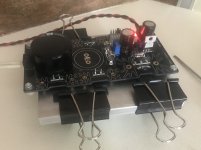
Just a plate without fins, not attached to chassis, covered with the PCB, hmm it will eventually go high. Do you have a lower secondary transformer for a test? Maybe you don't need all the headroom you now got? That would drop the dissipation. What DC you got across the 1N4007? Otherwise you would need a proper finned sink with correct orientation. Fins looking upwards along the hot air's move. Or double the plate. Even if you stand the build with solid plate you now got vertical on its small side it should lose some C. Try that to see if its primarily about mass or air circulation.
To try roughly calculate another plate in a certain assembly situation it takes to measure C/W above ambient for this one sample first.
To try roughly calculate another plate in a certain assembly situation it takes to measure C/W above ambient for this one sample first.
Just a plate without fins, not attached to chassis, covered with the PCB, hmm it will eventually go high. Do you have a lower secondary transformer for a test? Maybe you don't need all the headroom you now got? That would drop the dissipation. What DC you got across the 1N4007? Otherwise you would need a proper finned sink with correct orientation. Fins looking upwards along the hot air's move. Or double the plate. Even if you stand the build with solid plate you now got vertical on its small side it should lose some C. Try that to see if its primarily about mass or air circulation.
To try roughly calculate another plate in a certain assembly situation it takes to measure C/W above ambient for this one sample first.
thanks for helping 🙂
it's 5.9vdc across 1n4007. Ambient C is about 25-27c. The trafo is pretty warm I would say, but not hot. Unfotunately do not have any other to test with. Might it be less hotrod with 30VA toroid, for instance?
- Home
- Amplifiers
- Power Supplies
- L-Adapter