Don't worry about the max RMS gen output, you may set 1.5VRMS to same experimental effect as to my examples effect. The transformer ratios will manifest the same. What you want is enough signal at the secondaries for the scope channels to capture two clean synchronized sinewaves.
Don't worry about the max RMS gen output, you may set 1.5VRMS to same experimental effect as my examples. The transformer ratios will manifest the same. What you want is enough signal at the secondaries for the scope channels to capture two clean synchronized sinewaves.
Ok, understood. Thank you for the support.
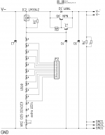
First thing that strikes me wrong in your schematic is the LM334's pin 2 should connect R1' to pin 3. Don't know about the rest. Without practical development, parts comparisons, electrical & subjective tests, I can't predict some equivalent spec compatible sounding negative.
But there is also another way. Two regular positive guaranteed identical L-Adapters can be connected up like batteries for dual polarity output with midpoint common. The official boards already have independent own bridge rectifiers and reservoir capacitors. They would also need dual independent AC secondaries for dual polarity setup. Not necessarily dual independent transformers.
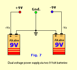
But there is also another way. Two regular positive guaranteed identical L-Adapters can be connected up like batteries for dual polarity output with midpoint common. The official boards already have independent own bridge rectifiers and reservoir capacitors. They would also need dual independent AC secondaries for dual polarity setup. Not necessarily dual independent transformers.
Thank you Salas,
I will have a relook into the design, probably drop the -ve rail idea.
regards
prasi
I will have a relook into the design, probably drop the -ve rail idea.
regards
prasi
Alright. Good luck and keep us posted.
Here is a completed one. Using the Kingbright DC10-YWA instead of the specc'ed DC10-EWA, CDE 6800uF capacitors, all onboard heatsinks and a 12VAC transformer (70VA) to deliver 5.1v for a RPi4.

Stable for hours, doesn't get very hot - could be that it is outside of a box, as well as the fact that my RPi4 has no HAT's and no external USB devices - running only Ropieee for a Roon Endpoint solution.
Looking for a suitable heatsink (or I will have to machine one) so that I can fit this in a 1U box with the proper standoffs.
Simply sinking Q2 to the box itself should suffice for such a minimal configuration Rpi use.
That will dramatically decrease complications, much appreciated.
I will probably put two separate L-Adapters in the box, but the second one is an optional PSU that "may" power an Intona isolator (which requires 5V / 500mA), so again minimal usage?
Yes 500mA is not much. Means only 1.25W dissipation for 2.5V across Q2. Just have a thick enough case with ventilation holes placed in a way to aid air circulation through it. It should thermally support those relatively light running L-A's without drama.
"Roughly 1.5V to 20V range" as it is. If with single IR LED could go lower maybe. But not tested.
What test exactly, some combination? Replacing an SMPS with the L-Adapter is what they usually do.
You can parallel all. I thought you might had meant four wires. Parallel in right phase. Else it will get hot fast and ultimately destroyed.
It takes a scope to confirm sinewaves match in timing.
When without a scope, start with two secondaries, if not getting hot add another then another. If getting hot reverse one in each move.
Hi
Back in my post #573, I received the trafo shown in the photo and not the ad
description, 0-115-220-SCN 4 wires.
I’m in the US and need 115VAC. I am outta luck here?
The SCN is just screen to earth ground for noise reduction? It is not
an actual tap?
I would think if I connect 115V to the two 220 red wires, then
secondaries only 4.5V. Series would bring it to 9V but not enough
current. :-(
Yellow/Green is static screen not a tap. You are stuck with a 220VAC primary. Ask for your money back.
Hey all,
Finally got my l-adapter assembled for my raspberry pi, and the thing is solid. No more "low voltage lightning bolt" thank you very much!
I realise I didn't have add an led to the front of the panel. Is everyone just tapping the outputs to supply an led?
Finally got my l-adapter assembled for my raspberry pi, and the thing is solid. No more "low voltage lightning bolt" thank you very much!
I realise I didn't have add an led to the front of the panel. Is everyone just tapping the outputs to supply an led?

- Home
- Amplifiers
- Power Supplies
- L-Adapter