@InSides,
According to the pics in the 1st post, there are many holes to receive VR1, the W (in line pins) should fit too.
According to the pics in the 1st post, there are many holes to receive VR1, the W (in line pins) should fit too.
@InSides,
According to the pics in the 1st post, there are many holes to receive VR1, the W (in line pins) should fit too.
Cool, thanks. So I will go with the P/N 652-3296W-1-501RLF.
What about alternatives to the Kingbright?
Many thanks!
1. The Kingbright LED graph is out of stock until late August it seems. But locally I have found a different Kingbright model (DC-10YWA). Is it OK to use this one as opposed to the DC-10EWA? Alternatively, could you suggest a suitable alternative currently in stock at Mouser?
It looks like it will replace fine because its forward current vs forward voltage chart is close to the EWA for results. Steeper in curve graph shape mainly which is good. Only it will be yellow.
It looks like it will replace fine because its forward current vs forward voltage chart is close to the EWA for results. Steeper in curve graph shape mainly which is good. Only it will be yellow.
Many thanks, looks like I am all set.
Now it is a waiting game.
Alright. Good luck and keep us posted.
Will do - it will probably be more than a month until everything gets here.
As parts are on the way, nothing to do but mock up an enclosure. And here is where I come to a conundrum.
I would like to have the enclosure at 1U (44mm). Wooden frame, top and bottom 3mm thick aluminium plates. This gives me net 38mm height, which means that I will not be able to install the PCB level heatsink on Q2.
This enclosure will hold 2 L-Adapters, both set for 5.1V (I expect around 2A max per PSU). Would you say I can get away with using the bottom plate as a heatsink?
Approximate dimensions for the bottom plate are 390mm x 310mm x 3mm, and would need to cool down 2 pieces of Q2. I had planned to do off-PCB heatsinks anyway, but trying to see whether I can save some space and use the bottom plate.
This may be a stupid idea as the bottom plate screws directly to the wooden frame (via wood inserts for machine screws, but still).
All PCBs will be mounted on nylon standoffs, and the transformer is potted, so mounted using a bolt from the underside.
Some breathing holes on top and bottom plates should help a lot.
The top panel is to be riddled with slots, that is a given. I did not plan on adding many (if any) to the bottom panel, but should be easy.
So:
1. I take it I can get away with the bottom panel as a heatsink - would you say bolt directly to it, or maybe use a small copper block between Q2 and the bottom panel?
2. I may need to extend Q2 via some short wires as opposed to soldering the pins directly to the PCB. I hope that is not an issue?
Thanks!
1. That big bottom panel should take it. Average load current matters most not peak. It needs (preferably aligned) holes for outside air to come through the bottom and go out via the top slots. Copper block is acceptable. If its long and wide enough to add thermal capacitance. Use liberal thermal paste on both copper sides to fill out the mating surfaces micro anomalies, and don't forget the electrical insulation for Q2s of course.
2. Small extension wires usually create no problems for Q2s but keep them as short as possible.
2. Small extension wires usually create no problems for Q2s but keep them as short as possible.
The LED array is out of stock. Can I use this part?
Mouser # 630-HLMP-2400
For 5V Output, is one led bar lit enough? Not sure what to start with.
I'm hoping to build this for RPI4. I ordered an R-Core 9V at .855A x4 from Ebay.
That should be ok?
If you use 10,000uF vs. 6800uF, ideally it should be cleaner supply?
30mm Diameter is max on the PCB?
Thank you 🙂
The Avago HLMP isn't compatible. Mouser states will have DC-10EWA Red & DC-10YWA Yellow (works too) in twenty days. Buy from Digi-Key has right now stock. 754-1176-5-ND & 754-1179-5-ND. Start with three lit bars and adjust the trimmer for 5.1 Volt. To offset output cable voltage drop.
Better parallel two 9V secondaries on that R-Core. What VA power it states? 30? You may use 10000uF filter caps no problem. Yes, 30mm max diameter.
Better parallel two 9V secondaries on that R-Core. What VA power it states? 30? You may use 10000uF filter caps no problem. Yes, 30mm max diameter.
You can parallel all. I thought you might had meant four wires. Parallel in right phase. Else it will get hot fast and ultimately destroyed.
It takes a scope to confirm sinewaves match in timing.
When without a scope, start with two secondaries, if not getting hot add another then another. If getting hot reverse one in each move.
It takes a scope to confirm sinewaves match in timing.
When without a scope, start with two secondaries, if not getting hot add another then another. If getting hot reverse one in each move.
Or if you do not have a scope, you can get such board below witch will help you to identify wires in any power transformer with several secondaries.
A little tester to determine transformer PhaseDots with no scope or signal generator
A little tester to determine transformer PhaseDots with no scope or signal generator
Last edited:
Or dim bulb tester to judge by the glow or sacrificial primary fuses or LCR for secondaries inductance null clue etc.
Hi Salas, i've just finished to build the linear power supply for phono box;Depending on what and how post regulators or switching converters inside he could possibly make a good upgrade by replacing an external SMPS for L-Adapter to a phono box. Lets see about his findings.
i used a toroidal 21V 30A (i already had this at home), output set at 18v.
The original SMPS was 18v 1A, there may be overheating problems with kit heatsinks and thermal paste?
What is the right temperature at your hopinion?
Thanks for every suggestions and sorry for my english..
Up to 60C on the L-Adapter's sinks should be manageable. But it could be less. Two ECC83 in that phono box can't pull more than 600mA parallel heaters current. Or no more than 300mA if in series.
Thanks for info on trafo phase 🙂
Anyway to tell with DVM?
That phase board is cool but I don’t ever do enough diy to make one of these.
I can get access to scope and sig. generator, is there a way to figure out the phase?
What is the super simple way? I won’t get the trafo any time soon though.
In this case of 4 windings, how would you test each one and know which wires are in phase?
I thought these simple transformers are all single phase type??
Where did you get the usb-c connector to make your own power cable for rpi4?
I guess I could just hack off one end of a retail USB-C cable, wires are kinda small in those.
Last edited:
DVM will show no AC voltage when secondary instantaneous polarities are paralleled opposite. Over-current and heating will be happening already if testing with high energy i.e. with the primary on mains. Dim bulb tester is safest way to know paralleling is wrong in this case. Big glow tells you to reverse one secondary while current limiting opposes high current draw to happen. Dim Bulb Tester
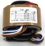
To know safely before hand with generator and scope, feed 2.3VRMS 50Hz via 1k series resistor to the primary*, probe the secondaries, one for each scope's channel. When sinewaves align on the screen you know each wire on a probe's nose is in phase. Put a dot on them with a marker pen. When paralleling secondaries connect dotted cables together and non dotted cables together.
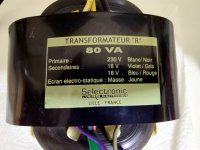
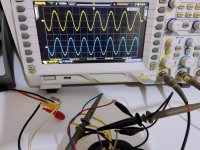
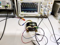
Example pictures from an R-Core of mine. Blue and violet proved in phase. Paralleled secondaries are the last picture. When I reversed wire colors mating, the yellow sinewave vanished and became a flat line. If colors were the same for each secondary pair I would have marked dots to distinguish.
*With that test signal each 10mV RMS scoped on secondaries will represent real life 1V RMS from unloaded secondaries when the transformer is for European Union mains. For USA mains transformer use 1.2V 60Hz signal.
To know safely before hand with generator and scope, feed 2.3VRMS 50Hz via 1k series resistor to the primary*, probe the secondaries, one for each scope's channel. When sinewaves align on the screen you know each wire on a probe's nose is in phase. Put a dot on them with a marker pen. When paralleling secondaries connect dotted cables together and non dotted cables together.
Example pictures from an R-Core of mine. Blue and violet proved in phase. Paralleled secondaries are the last picture. When I reversed wire colors mating, the yellow sinewave vanished and became a flat line. If colors were the same for each secondary pair I would have marked dots to distinguish.
*With that test signal each 10mV RMS scoped on secondaries will represent real life 1V RMS from unloaded secondaries when the transformer is for European Union mains. For USA mains transformer use 1.2V 60Hz signal.
Attachments
- Home
- Amplifiers
- Power Supplies
- L-Adapter