russc you have it spot on.
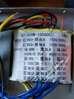
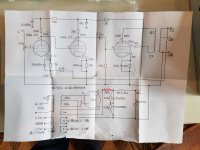
The transformer in the kit vishalk has is now clearly the incorrect one for that kit. Now I expand the picture from vishalk you can also see 3 x 5.0 volt secondaries, not 1 x 5.0 volt and 1 x 6.3 volt as well as the 400-0-400 when it should be 350-0-350.
Vishalk - sorry to say you will have to get them to replace it. It is the wrong one for that kit.
Attachments
The pics in post 1 were what the supplier sent to aid his assembly.
Not pics of the actual transformer supplied.
We must wait for Vishalk to tell us which transformer he has.
Not pics of the actual transformer supplied.
We must wait for Vishalk to tell us which transformer he has.
russc you have it spot on.
The transformer in the kit vishalk has is now clearly the incorrect one for that kit. Now I expand the picture from vishalk you can also see 3 x 5.0 volt secondaries, not 1 x 5.0 volt and 1 x 6.3 volt as well as the 400-0-400 when it should be 350-0-350.
Vishalk - sorry to say you will have to get them to replace it. It is the wrong one for that kit.
Alan you don't have to tell me mate, that is the transformer and yes you're right it does not have 1 x 6.3 volts. The voltage is also 400v! I just assumed the 5v would be ok to use for the rectifier.
Will this really make a difference? Or should i just wait and get them to send the right one.
Hi vishalk,
Pity we didn't spot it earlier, but YES you have to get the correct one.
(No excuse, but the pictures aspect ratio is wrong on the early posts and it is difficult to see the secondary values unless you 'expand' it...)
That 400 volt winding will result in an HT (B+) voltage too big for the supplied caps and you need the 6.3 volts for the 6N8s. Plus the proper transformer has a 240 volt mains selection... and so on.
Don't even consider using it now. The supplier will replace it for the correct one I'm sure .

You know you can slap band aids on it, like current limiters, and a bucking transformer, but seriously you should ask yourself why? All those tricks would not be necessary if you had the correct PT. And if no one holds the seller to provide the correct parts for the kit then they will just carry on leaving everyone with a bad experience.
I am sure you paid with Paypal, which can also help you with resolving any problems if it comes to that.
I am sure you paid with Paypal, which can also help you with resolving any problems if it comes to that.
You're right dak808, i have messaged the seller with pictures and told them it needs sorting out. Specified i need 240v 350-0-350, 6.3v, 5v and 3.15.
Hi, i am wiring the scheme. I bought all component by myself but I don't know the input impedance of the two output transformer. Can you precise me this impedance (2,5 k ohms or 3,5 kohms or something else). Best regards.
The good thing with ebay is you can tell them the instructions are not suitable. The seller has to fix your issues or your money back. If your missing bits again the seller has to sort this out.
Hello, I did not bought the kit. I have all the components except the output transformers. I need to know the primary impedance of the output transformers to buy the suitables transformers : I guess 3,5 k ohms but i'm not sure. I hope Vishalk can say it to me. Best regards.
Suggestion: Go to Blueglow Electronics on YouTube and watch the 10 or 11 segment video on how he builds a KT88 single end amplifier. Your schematic will be different, but rather similar. His explantions, guide and video are exceptionally detailed and super helpful and educational.
Anything 3.5k to 5k will do as long as its SE not PP as a PP may saturate.
3500 Ohm Single ended 10W Output transformer (KT88 or similar) – Primary Windings
3500 Ohm Single ended 10W Output transformer (KT88 or similar) – Primary Windings
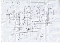
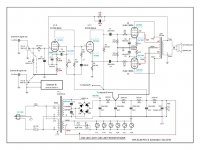
I purchased ChiFi PP amp last April. (Schematic posted below).They must use same diagramming company as mine by the looks of it. I was able to complete my amp by the schematic provided, but wouldn't recommend anyone buying the DIY kit unless fluent w/diagrams.
Per your Power trans issue, try adding power resistor- my kit came w/75 ohm 25W(yellow X in pic) to the 400/400 center tap line. It dropped 53V in my design. Others may be able to advise better value than that.
You will get it going- you're at the right place for help.
Jim
Per your Power trans issue, try adding power resistor- my kit came w/75 ohm 25W(yellow X in pic) to the 400/400 center tap line. It dropped 53V in my design. Others may be able to advise better value than that.
You will get it going- you're at the right place for help.
Jim
Attachments
Hello. Do you thonk that ground (black) way is correct to avoid noise ?View attachment SchemaKT88.pdf
View attachment ImplantationKT88V4.pdf
View attachment ImplantationKT88V4.pdf
Hello. Do you thonk that ground (black) way is correct to avoid noise ?View attachment 908160
The new GND reference point would have to be after the resistor- Not sure of impact on noise.
Another option would be to place in circuit where red resistor label is added.
Attachments
oemcar,
Your Post # 54 schematic has an interesting twist:
The concertina has 30k in the cathode, and 27k in the plate.
That creates un-equal signal amplitudes to the output tubes Push (27k times concertina signal current), and Pull (30k times concertina signal current).
That becomes 2nd harmonic distortion, and 2nd order intermodulation distortion.
The negative feedback reduces those two distortions.
Just something most do not think about.
Now, perhaps, the designers noticed that with equal concertina cathode and plate resistors, the signal amplitudes were un-equal.
If so, that would be caused by filament to cathode leakage resistance in parallel with the cathode resistor.
The problem with using un-matched cathode and plate resistors, is that the filament to cathode leakage resistance is not a constant, it varies from tube to tube, and also with the age of the tube.
The only solutions with this problem is to use equal cathode and plate reistors, and then . . .
Pick a tube that has very large maximum cathode to filament voltage rating (including the DC and peak signal swing on top of that);
and if necessary to elevate to the proper voltage to keep the DC and peak voltages of the cathode to be within the cathode to filament specs.
Last edited:
oemcar,
Your Post # 54 schematic has an interesting twist:
The concertina has 30k in the cathode, and 27k in the plate.
That creates un-equal signal amplitudes to the output tubes Push (27k times concertina signal current), and Pull (30k times concertina signal current).
That becomes 2nd harmonic distortion, and 2nd order intermodulation distortion.
The negative feedback reduces those two distortions.
Just something most do not think about.
Now, perhaps, the designers noticed that with equal concertina cathode and plate resistors, the signal amplitudes were un-equal.
If so, that would be caused by filament to cathode leakage resistance in parallel with the cathode resistor.
The problem with using un-matched cathode and plate resistors, is that the filament to cathode leakage resistance is not a constant, it varies from tube to tube, and also with the age of the tube.
The only solutions with this problem is to use equal cathode and plate reistors, and then . . .
Pick a tube that has very large maximum cathode to filament voltage rating (including the DC and peak signal swing on top of that);
and if necessary to elevate to the proper voltage to keep the DC and peak voltages of the cathode to be within the cathode to filament specs.
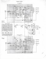
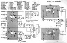
I've heard that before w/ the ChiFi design you reference. Makes sense to balance these in a phase splitter(concertina)to equally load the AC sig to the PP output pentodes.
Next design built was Audio Note EL84, which, as you can see below, were balanced. Then Dynaco ST-35 (also SCA-35) which aren't....
Point of interest-
Both Dynaco designs have RC path between cathodes that Audio Note doesn't. Could this factor into the balance?
Jim
Attachments
- Home
- Amplifiers
- Tubes / Valves
- KT88 Valve Tube Amplifier Single-ended Amp DIY KIT from China. No instructions!