Well done lumanauw,
You were the first to spot this but it went unheeded - could this be one of the major characteristics of this circuit? It seems to answer the non-switching argument by the slow turn-off characteristic of the O/P transistors - maybe more investigation is warranted.
The other point I think that everyone is missing is that Steve was talking about a 400W amp for the specs he gave not the amps we're talking about here. Who knows what tricks this 400W amp has up it's sleeve - he certainly wasn't allowed to develop this basic concept amp through it's different generations as he had said he intended
Edit: Here's what Charles Hansen said about this very thing
The odd thing is that (unlike just about every other output stage around), there is nothing tying the two driver transistors together. Normally there would be a resistor from emitter-to-emitter (in a good design that keeps the drivers in class A) or resistors that tie to the output stage (in a less-good design that lets the drivers go into class B along with the outputs).
I've listened to differering resistor values at that location, and all I can say is that using no resistor there made for quite a strong (but pleasant!) sonic signature.
Hi,
may I pollute the air again? For best sonic performance, I would forward bias the drivers so they conduct during the whole signal cycle.
may I pollute the air again? For best sonic performance, I would forward bias the drivers so they conduct during the whole signal cycle.
Hi. That seems a very sensible suggestion on the face of it.Lumba Ogir said:Hi,
may I pollute the air again? For best sonic performance, I would forward bias the drivers so they conduct during the whole signal cycle.
Thought experiment. Suspend disbelief and assume that this makes the performance of the OPS worse. Even though the drivers are now operating in a more linear region. What else is going on? What could the trade-off be?

jkeny said:Well done lumanauw,
You were the first to spot this but it went unheeded - could this be one of the major characteristics of this circuit? It seems to answer the non-switching argument by the slow turn-off characteristic of the O/P transistors - maybe more investigation is warranted.
The other point I think that everyone is missing is that Steve was talking about a 400W amp for the specs he gave not the amps we're talking about here. Who knows what tricks this 400W amp has up it's sleeve - he certainly wasn't allowed to develop this basic concept amp through it's different generations as he had said he intended
Edit: Here's what Charles Hansen said about this very thing
.....I've listened to differering resistor values at that location, and all I can say is that using no resistor there made for quite a strong (but pleasant!) sonic signature.
so, what about "pleasant sound" or "sonic signature" WITH resistor ?
lumanauw said:Hi, EDDELARUE,
This crossconduction is the indication of non-turnoff. If you make this crossconduction disappear (by putting R10-100ohm), you are spoiling non-turnoff properties (at higher frequencies) of this circuit.
Could you check simulated THD of 20khz or 50khz signal with and without this R10=100ohm?
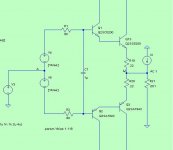
This Hiraga amp also don't use base bleeder resistors at base of 2SD844 and 2SB754
Hi lumanauw,
Yes, later I will post some results of my simulations for answer your question.
regards
Ed
traderbam said:Hi Scott,
Do you mean, instead, sit down at a water board? Talk about pulling teeth. 😛
Did you mean, holding their Vbs constant?
IOW, the transconductance of the output transistors on their own, with 25mA bias, is so non-linear that 50ppm into 8 ohms is not even possible in theory?
Brian
You beat me to it 🙂
OK one more time...
>Third and fourth paragraph: The AC voltage between the emitters of the bias pair remains constant (well very close). I thought I had answered your last question. I may have done that in a thread started on another DIY site. There is not an AC voltage drop across that cap. If you look at either side of the cap, you will see an exact replica of the input signal throughout the entire cycle. If you look at both sides of the cap differentially, there is no signal .<
Let's forget 20kHz and look at DC or low frequencies, the cap would be between my VA and VB in attached schematic (please keep in mind above bolded text). The plot is the deviation from a straight line of the input vs output, about .1V peak on a 20V peak signal. This is the simple logarithmic relationship between Vbe and Ic for any transistor.
Attachments
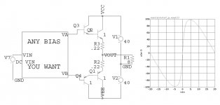
Another factor (possibly far fetched) is that the diodes in the bias chain have "bleeders" across them and the actual diode voltage is only around 200mV. This arrangement won't even closely track over temperature. At full power the bias could thermally walk up to a much higher level than when cool.
I'm not trying to make anyone look foolish here, there could be a very easy to miss simple oversight.
I'm not trying to make anyone look foolish here, there could be a very easy to miss simple oversight.
scott wurcer said:You beat me to it 🙂
OK one more time...
That is clear. "Any bias you want"

I have been analyzing the output resistance of the bias circuit. It is highly dependent on transistor choice (the specific turn-on region Ic vs Vce curves) but looks like it will typically range from 20 ohms to 120 ohms or so. My ZTX458 model gives about 80 ohms. It will depend upon the current source values and the specific output transistor types too.
I mention this because series resistance is important to the dynamic linearity of the darlingtons. So don't overlook these when you consider alternative bias schemes. The 1uF cap should be on the driver side of the series resistors.
Brian
Attachments
Has anyone else tried simulating with those 2SC5200 and 2SA1943 models?
I've had a go (used them for both drivers and outputs). The models don't seem to be especially complementary for some reason. I'm getting about 500ppm at 10kHz, 30Vpk, 8ohms. By cheating a lot (conjuring up perfect complements for all transistors) I managed to get it to 130ppm.
Brian
I've had a go (used them for both drivers and outputs). The models don't seem to be especially complementary for some reason. I'm getting about 500ppm at 10kHz, 30Vpk, 8ohms. By cheating a lot (conjuring up perfect complements for all transistors) I managed to get it to 130ppm.
Brian
Steve Dunlap said:
Hmmm - Sunforce http://www.sunforce.com/specials.htm is having a special on "Test Designer" - only $13,800.00

ISSpice is based on the same sparse matrix solver as any of the common Spice variants. Within reason the solution is unique especially at DC and low frequencies so for the same set of supported model parameters they get the same answer. After all it is just a VERY BIG set of N equations and N unknowns.
scott wurcer said:ISSpice is based on the same sparse matrix solver as any of the common Spice variants. Within reason the solution is unique especially at DC and low frequencies so for the same set of supported model parameters they get the same answer. After all it is just a VERY BIG set of N equations and N unknowns.
Scott,
The easiest job for all simulators is the AC/Noise analysis. That's because the simulator deals only with a linear system and all it has to do is to solve the sparse matrix system. I am not aware of any incarnation that does anything different to the original Berkeley Spice in this regard. Some simulators are providing alternate algorithms, but this ever barely improves the performance.
DC and transient analysis are different though. Before using the same sparse matrix system the simulator has to linearize the nonlinear equation set. This is where various algorithms are used, essentialy because the original Berkeley was poor. I used to run a few trivial examples of circuits that may cause deep trouble in this part, all based on negative impedance, having two stable solutions and watch how the simulators are flipping or crashing... This is a good candidate where simulators can provide divergent results, however I have never seen this happening in Krill type circuits. This type of circuits though can be very sensitive to model parameters, as is any circuit that relies on beta or Is to define the output. Therefore, as you mentioned, I'm pretty sure that using consistent models will provide consistent results on the Krill analysis. I have an old(is) version on ISSpice, I have just tried the Krill DC, and got essentially the same results as in my reference PSpice. Not being a LTSpice fan (only because I have other more convenient (and legally licensed) options) I can't unfortunately further confirm the results consistency.
Bottom line, the issue appears to be the models used to simulate Krill, rather than the simulator itself. A long message for a pretty obvious conclusion 🙂
c2cthomas said:
Hmmm - Sunforce http://www.sunforce.com/specials.htm is having a special on "Test Designer" - only $13,800.00
I never said it was free.
syn08 said:
Bottom line, the issue appears to be the models used to simulate Krill, rather than the simulator itself. A long message for a pretty obvious conclusion 🙂
Thanks for the details. BTW I was the one who pointed out to Pease that an opamp will converge perfectly at DC with the inputs swapped. 🙂
scott wurcer said:
Thanks for the details. BTW I was the one who pointed out to Pease that an opamp will converge perfectly at DC with the inputs swapped. 🙂
With his well known love for computers, I bet Bob was delighted by your observation

I spent some time today simulating my circuit with some of the suggested improvements made on this thread. First, I simulated my circuit as I designed it. I am not ashamed of the simulated THD. It seems to agree quite closely with my measured results.
Some obvious observations:
The posted VGS is far better than some have claimed.
None of the recommended improvements showed an improvement in THD.
If you can't duplicate my results, that is not my problem.
I will not post my models. I bought them, but according to the licensing agreement I can not distribute them.
Steve Dunlap said:I spent some time today simulating my circuit with some of the suggested improvements made on this thread. First, I simulated my circuit as I designed it. I am not ashamed of the simulated THD. It seems to agree quite closely with my measured results.
Some obvious observations:
The posted VGS is far better than some have claimed.
None of the recommended improvements showed an improvement in THD.
If you can't duplicate my results, that is not my problem.
I will not post my models. I bought them, but according to the licensing agreement I can not distribute them.
Hi Steve,
Whose models are you using? There's a good chance that someone else on this forum has access to those models as well.
Thanks,
Bob
Steve Dunlap said:I spent some time today simulating my circuit with some of the suggested improvements made on this thread. First, I simulated my circuit as I designed it. I am not ashamed of the simulated THD. It seems to agree quite closely with my measured results.
Some obvious observations:
The posted VGS is far better than some have claimed.
None of the recommended improvements showed an improvement in THD.
If you can't duplicate my results, that is not my problem.
I will not post my models. I bought them, but according to the licensing agreement I can not distribute them.
Very good! Could you please:
- Post the schematic you are using for simulation purposes.
- List the models you are using and the source(s) you purchased them from. I am positively sure I can help with that, I know lots of people in the industry that could grant us free access to these models, for non-commercial use as DIY.
- Tell us your simulation results.
We could then have a common platform for analyzing your circuit.
- Status
- Not open for further replies.
- Home
- Amplifiers
- Solid State
- Krill - The little amp that might...