Lumba Ogir said:jkeny,
I cannot estimate its dynamic behavior but it is quite indifferent to me because of the meager outcome, even working perfectly. An approach aiming to substantially reduce crossover distortion in class B would be much more sexy and challenging. (With some kind of error correction, however, due to its harmful character, paying great attention to signal integrity. This would be something for people like traderbam and Jan).
So again your dismissing a circuit that you state you don't even know how or the extent to which it works or care for that matter - although you do know that it's outcome is meagre - do you not see the folly of posting this here? If you don't care why bother posting?
jkeny,
please read this again and try to understand the meaning and the consequences of the statements.
http://www.diyaudio.com/forums/showthread.php?s=&threadid=139796
please read this again and try to understand the meaning and the consequences of the statements.
http://www.diyaudio.com/forums/showthread.php?s=&threadid=139796
but it is quite indifferent to me because of the meager outcome, even working perfectly.
Lumba, with respect, John is correct, this is silly. This is a machine for amplifying music; it should be judged both as a piece of engineering and for its intended purpose - a good listening session. It might even be superior to a Class A amp, who knows?
When you simulate a Class AB amp and probe the current through the base stoppers on the outputs, you find two short term glitches, around 0.8uS microsecond each at 20KHz signal, which show oscillatory charge flow into the base junction at around 9Vp and again at 3Vp.
There is no sign of voltage oscillation at this point, or indeed current oscillation at the output emitter resistors, so I assume the effect is minimised if the drivers give low impedance sourcing.
This is perhaps more a factor for improvement in amp design, rather than worrying too much about crossover distortion. This is related, but not quite the same thing, as examination of the waveforms at crossover in a well designed amp is damn smooth.
Cheers,
Hugh
Hugh,
What could it provide in a class A amp where neither switching distortion nor crossover distortion can on principle occur?It might even be superior to a Class A amp, who knows?
Lumba,
You are right on principle, but you have not heard it - nor have I. It might be a revelation, who knows? One can condemn a Ferrari on engineering principles for lack of engine durability, but when you drive one, WOW!! Keep an open mind......
Cheers,
Hugh
You are right on principle, but you have not heard it - nor have I. It might be a revelation, who knows? One can condemn a Ferrari on engineering principles for lack of engine durability, but when you drive one, WOW!! Keep an open mind......
Cheers,
Hugh
Hugh,
It is predictable. (Not everything is).You are right on principle, but you have not heard it
Lumba Ogir said:Hugh,
It is predictable. (Not everything is).
So no chance of an open mind then? Why are you wasting your time on this thread when it's obvious we are all idiots here?
I sort of feel it is time for us to stop wasting effort and space on the switching debate. There are more interesting fish to fry. Enough already.
I think those striving to explain, in multiple ways, why switching can and will occur are just trying to stop innocent bystanders being misled by poorly considered conjecture and muddled thinking.
Simple maths shows it switches, simulation shows it switches, and common sense shows it switches. Why deny it? This doesn't detract from the very low THD claims.
What I do know is that the bias scheme is unusual and provides a simple way to adjust the bias current in the o/p transistors in order to flatten the cross-over characteristic. That's all it does. Just like a conventional bias scheme. There are some subtle side-effects, but I won't muddy the waters with these now.
The 0.005% THD has not yet been verified within this thread but SD assures us he measured it on the bench many moons ago. I am open-minded. The LTSpice model doesn't achieve it but why would it when it is using the wrong models? I think this is area much more interesting.
Brian
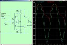
The sim below shows the OPS driving 30Vpk into 4-ohms at 1HZ. Blue is the npn driver Vbe. Red is the npn o/p transistor Vbe. Green is the input signal. The driver BE is briefly reverse biased by more than 1.1V.
I think those striving to explain, in multiple ways, why switching can and will occur are just trying to stop innocent bystanders being misled by poorly considered conjecture and muddled thinking.
Simple maths shows it switches, simulation shows it switches, and common sense shows it switches. Why deny it? This doesn't detract from the very low THD claims.
What I do know is that the bias scheme is unusual and provides a simple way to adjust the bias current in the o/p transistors in order to flatten the cross-over characteristic. That's all it does. Just like a conventional bias scheme. There are some subtle side-effects, but I won't muddy the waters with these now.
The 0.005% THD has not yet been verified within this thread but SD assures us he measured it on the bench many moons ago. I am open-minded. The LTSpice model doesn't achieve it but why would it when it is using the wrong models? I think this is area much more interesting.
Brian
The sim below shows the OPS driving 30Vpk into 4-ohms at 1HZ. Blue is the npn driver Vbe. Red is the npn o/p transistor Vbe. Green is the input signal. The driver BE is briefly reverse biased by more than 1.1V.
Attachments
Hugh,
we need this kind of trickery when we try to gain efficiency, but it cannot be done unpunished according to the incorruptible laws of physics.
we need this kind of trickery when we try to gain efficiency, but it cannot be done unpunished according to the incorruptible laws of physics.
Once again people are criticizing the design by hypotheses, probably without full understanding of how it works, may be without caring about how it works, definitely without building it + measuring it + listening to it.
Anyhow, it seems that judging this design as a regular class B, or class AB is erroneous. This is a unique design and it shouldn't be confused with other conventional designs.
Also, when simulation software are failing to deal correctly with this unique design, why continue judging it only by simulation?
It looks like enough is enough.
It seems that discussing the design is welcomed. So, let's discuss the design. Let's begin by understanding how it works.
I admit, I don't understand fully how this unique design works.
Anyone is willing to explain it to me, and may be to some others?
andy_c said:I won't do that part as this post is already too long.
No need, your explanation is sound as usual.
I was wondering whether we could improve the LTSpice models so as to get closer to the claimed THD figures. The 2SC5300 and 2SA1943 are quite different from the 0281 and 0302 and much better complements, AFAICS from the Toshiba datasheets.
Do you have any clues where to get LTSpice models for these?
Brian
traderbam said:
I was wondering whether we could improve the LTSpice models so as to get closer to the claimed THD figures.
Is it possible that the inaccuracy here isn't only due to inaccurate models?
traderbam said:The 2SC5300 and 2SA1943 are quite different from the 0281 and 0302 and much better complements, AFAICS from the Toshiba datasheets.
Do you have any clues where to get LTSpice models for these
Fairchild has them. I just filled out their forms to have them sent to me, but either their mail system or mine is slow and I haven't received them yet.
Andy,
I second Brian's request, I'd really appreciate some good models for the 5200/1943 outputs and the 2SC3423, they are all I use.
I have found simulation a useful tool. It tells me little of the sound quality, of course (although the FFT is seriously cool) but it greatly accelerates development.
But it does make me lazy figuring currents and voltages in my head, and this might be a bad thing......
Cheers,
Hugh
scott wurcer said:I have also noticed another property of this circuit that really is different. The common mode level of the drive to the output stage is not driven as stiffly as when there is a follower directly connected to it. The base charge moving around can make it move and this then appears in series with the input. I don't see this doing anything here but with real devices who knows? I only mention it because it would not be the first thing I would measure.
This also would qualify as a fortuitous empirical artifact if in fact there was some cancellation.
Yes indeed. This is what I referred to in my post 1132. I have looked into the nature of this non-linear resistance because I initially hoped that it would work to cancel out some of the distortion in the drivers/ops. However, I find the non-linearity works in the wrong direction and so it only adds to distortion. This may be a pretty small artefact however - I haven't evaluated it. It can be mitigated simply by putting large caps across the CE of the bias transistors. BTW, in some of SD's circuits you'll recall he deliberately introduces more series resistance as part of an op offset adjustment, so he seems happy to prescribe somewhat arbitrary series resistance, without concern for imbalance.
Brian
I honestly think the real advances in understanding this circuit will only begin when a working model is put through rigorous measurements - then the normality or uniqueness of this circuit can be judged & the hypotheses tested.
Until then it's interesting to discuss things with an OPEN MIND leaving dictatorial attitudes to one side. Audio reproduction is part science & part art (ie the bits we don't understand scientifically) the ratio between these two often causes lots of argument but let's not become fanatical about either position. Fanaticism is not a good thing in this world as we have seen many times in history.
Until then it's interesting to discuss things with an OPEN MIND leaving dictatorial attitudes to one side. Audio reproduction is part science & part art (ie the bits we don't understand scientifically) the ratio between these two often causes lots of argument but let's not become fanatical about either position. Fanaticism is not a good thing in this world as we have seen many times in history.
I'm very willing to help anyone. I don't guarantee to be good at explaining my thoughts, though. I posted a terse (maybe too terse!) summary of my analysis of the bias circuit in post 1132, if that's what you are interested in. I haven't looked at the i/p stage.Joshua_G said:I admit, I don't understand fully how this unique design works.
Anyone is willing to explain it to me, and may be to some others? [/B]
Anything is possible. Do you have something specific in mind? I like to deal with the discrepancies I know about first and then see where that gets me.Is it possible that the inaccuracy here isn't only due to inaccurate models?
andy_c said:
Fairchild has them. I just filled out their forms to have them sent to me, but either their mail system or mine is slow and I haven't received them yet.
I think I got these from Fairchild quite some time ago; AFAIK Fairchild is no longer manufacturing these.
.MODEL Q2SC5200 NPN (
+ IS =4.3031E-12
+ BF =152.1
+ NF =1.0
+ BR =6.155
+ NR =1.028
+ ISE =1.3924E-11
+ NE =1.5
+ ISC =2.7542E-11
+ NC =1.95
+ VAF =60.0
+ VAR =6.51
+ IKF =10.8637
+ IKR =0.1585
+ RB =2.47
+ RBM =0.02
+ IRB =0.08
+ RE =0.04
+ RC =0.015
+ CJE =5.8111E-9
+ VJE =0.6506
+ MJE =0.3357
+ FC =0.5
+ CJC =6.4394E-10
+ VJC =0.5
+ MJC =0.3966
+ XCJC =0.7624
+ XTB =1.0445
+ EG =1.1663
+ XTI =3.0 )
.MODEL Q2SA1943 PNP (
+ IS =3.5476E-11
+ BF =159.9
+ NF =1.0
+ BR =25.75
+ NR =1.011
+ ISE =2.5119E-10
+ NE =2
+ ISC =7.9433E-11
+ NC =1.37
+ VAF =60.0
+ VAR =11.07
+ IKF =2.8370
+ IKR =0.3548
+ RB =2.74
+ RBM =0.0381
+ IRB =3.6308E-3
+ RE =0.06
+ RC =0.01
+ CJE =4.1783E-9
+ VJE =0.6354
+ MJE =0.3374
+ FC =0.5
+ CJC =1.1383E-9
+ VJC =0.5
+ MJC =0.3699
+ XCJC =0.7624
+ XTB =1.5306
+ EG =1.1751
+ XTI =3.0 )
- Status
- Not open for further replies.
- Home
- Amplifiers
- Solid State
- Krill - The little amp that might...