KSTR said:
Only way to get out of here to sim the thing thoroughly and carefully with the best models we can find (like andy_c's OnSemi Power-BJTs, etc) and then countercheck this with a real prototype. We just don't know yet, that's all.
Well said, like you I took Steve on his word and set out to help find the mechanism if any for this behavior. The almost daily changes to the circuit just confused things. This is not a complicated case, once you have settled on a circuit build it and compare the dynamic node voltages between the physical circuit and the sim.
This is a case of measurable quantifiable claims not the sonic differences between Dale and Vishay resistors.
I hope you can get to the bottom of it.
traderbam said:To: andyc
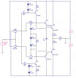
Andy, I was comparing your simulation model (post 846) with the most recent (I think) of Steve's 50W schematics. In the latter, Steve uses power transistors (2SC5200 & 2SA1943) for both outputs and drivers...your Q14 and Q13 and Q15 & Q16. Your model, on the other hand, uses low power transistors for the drivers. I know you are very conscientious about details so this inconsistency caught my eye.
I have never seen a circuit before that uses the same power transistors for both output and drivers. This is an expensive thing to do so Steve must have a good reason for it. I'm curious about this.
Hi Brian,
That sim was originally created by ostripper (OS). Steve then pointed out that OS had changed the topology a bit, making it slightly different from Steve's schematics. Steve also pointed out that nobody had tried to optimize the distortion in the sim. So I decided to take OS' sim, make the topology corrections noted by Steve, and attempt a distortion optimization in the sim by tweaking the bias. In that sense, it was a kind of proof of design thing, with the intent that if people saw merit in it, they could develop it further.
I believe OS got the MJE340/MJE350 models from Fairchild. As mentioned earlier in the thread, to get accurate saturation characteristics often requires that the quasi-sat parameters of the model (QCO, VO, etc.) be specified. I've tried other models that specify the quasi-sat parameters in those positions, but I got oscillation in the sim and didn't pursue it further.
Andy:
Thanks. I am sure you are right. I am not familiar enough to tweak model parameters myself...at this stage.
Klaus:
I found that ZTX458 and ZTX558 models have a persuasive and significant saturation characteristic. Trying these in the circuit and readjusting Rbias to about 5.5k lead to a Gm THD into a short of 0.9% with output current of 3.5A peak. When I shorted them out with 1F caps I saw no significant change to the spectra.
scott wurcer said:
This is a case of measurable quantifiable claims not the sonic differences between Dale and Vishay resistors.
I hope you can get to the bottom of it.
By simulation, or by measuring the actual circuit?
I've built the output stage:
All I have is a scope, but it certainly looks good. 1k sinewave:
A little blurry, but I was shaking with excitement...! 🙂
20k squarewave:
A little ringing on the bottom, but...wow...this looks good to my untrained eye.
It is driven by my function generator at 20Vpp. Power is +/-30V from my lab supply.
Schematic:
An externally hosted image should be here but it was not working when we last tested it.
All I have is a scope, but it certainly looks good. 1k sinewave:
An externally hosted image should be here but it was not working when we last tested it.
A little blurry, but I was shaking with excitement...! 🙂
20k squarewave:
An externally hosted image should be here but it was not working when we last tested it.
A little ringing on the bottom, but...wow...this looks good to my untrained eye.
It is driven by my function generator at 20Vpp. Power is +/-30V from my lab supply.
Schematic:
Attachments
Hi MJ,
does your scope have dual beam or dual trace?
Show both the input signal and the output signal simultaneously.
That overshoot might be at your input.
0.7mA through the diodes might be too low.
How about shorting out one of the 39k?
does your scope have dual beam or dual trace?
Show both the input signal and the output signal simultaneously.
That overshoot might be at your input.
0.7mA through the diodes might be too low.
How about shorting out one of the 39k?
Hi Andrew,
It's a 4 channel scope but I only have one probe. 🙁
Looking at the snakes nest of the construction, it's a wonder it runs at all...
(the above is a reference to my own work as seen on the previous posts, not a disparaging remark about anyone else's construction results or methods and my comments should not be taken out of context. Thank you)
AndrewT said:
0.7mA through the diodes might be too low.
How about shorting out one of the 39k?
It's Steve's design remember, not mine.
I had some time this morning and decided to experiment. I used values that I had on hand.
MJL21193 said:
It's Steve's design remember, not mine.
I had some time this morning and decided to experiment. I used values that I had on hand.
Are the values you used the same as Steve's desןgn?
Hi John
Nice.
Try to put a resistor between the emitter of the input transistors and collectors of the (bias) transistors (50 ohm), it simulates a lot better with these resistors.
Cheers
Stinius
Nice.
Try to put a resistor between the emitter of the input transistors and collectors of the (bias) transistors (50 ohm), it simulates a lot better with these resistors.
Cheers
Stinius
but you have reduced the voltage to +-30Vdc.
The diodes would pass [ Vcc+|Vee| - 4*Vf ] / [39+39]
@+-40Vdc that would be 1mA
@+-50Vdc that would be 1.2mA
The diodes would pass [ Vcc+|Vee| - 4*Vf ] / [39+39]
@+-40Vdc that would be 1mA
@+-50Vdc that would be 1.2mA
Joshua_G said:
By simulation, or by measuring the actual circuit?
I thought I made that clear.
>This is not a complicated case, once you have settled on a circuit build it and compare the dynamic node voltages between the physical circuit and the sim.<
Hi Stinius,stinius said:Hi John
Nice.
Try to put a resistor between the emitter of the input transistors and collectors of the (bias) transistors (50 ohm), it simulates a lot better with these resistors.
Cheers
Stinius
we have had a big falling out because folk do not seem able to accept that the sims are not modeling this topology accurately/closely/loosely/not at all.
Why should we believe what your sim is predicting?
Joshua_G said:
Are the values you used the same as Steve's desßgn?
Not quite...
stinius said:Hi John
Nice.
Try to put a
AndrewT said:but you have reduced the voltage to
Hi stinius, Andrew,
I'm not taking requests. To be blunt: build your own! 🙂
(please do not take my comments above in the wrong way - they were meant to be humorous and should be treated that way. Thank you)
Hey guys we're finally talking about a real working circuit with real working parts that know how to simulate themselves - well done - now that wasn't hard was it (only page 38 of thread)
Seriuosly, MJL, hat off to you for building this - let the fun now begin!
Seriuosly, MJL, hat off to you for building this - let the fun now begin!
AndrewT said:
Why should we believe what your sim is predicting?
My sim predicts what I have now. I don't have a THD meter to check that, but I don't expect it to be much different from what the simulator is saying.
AndrewT said:
Hi Stinius,
we have had a big falling out because folk do not seem able to accept that the sims are not modeling this topology accurately/closely/loosely/not at all.
Why should we believe what your sim is predicting?
Andrew
I agree that LTspice have some problems with this circuit.
For those interested I can recommend to read the following:
IEEE Journal On Solid State Circuits, Vol 31, No 1 January 1996
“Advanced modelling of distortion effects in bipolar transistors using the Mextram model”
The modelling of distortion effects in bipolar transistors due to the onset of quasi-saturation is considered.
John
If Steve would answer I think he would agree about these resistors.
Cheers
Stinius
stinius said:
Try to put a resistor between the emitter of the input transistors and collectors of the (bias) transistors (50 ohm), it simulates a lot better with these resistors.
I tried it on my sim and it drove distortion up. What did it do in your sim?
jkeny said:Seriuosly, MJL, hat off to you for building this
No hard feelings. 🙂
Way to go MJ. 
Say, have you got any more power transistors? According to SD's schematics, he uses them for the drivers too. Must be a good reason for this...
Say, have you got any more power transistors? According to SD's schematics, he uses them for the drivers too. Must be a good reason for this...
He posted earlier that it was to make mounting easier. (they are the same thickness as the main outputs)
Actually, NAD 2200 and 2600 use 2SC3281/2SA1302 as drivers so it's not unheard of in amps for domestic use. In PA amps 2SC5200-size devices are more often than not used as drivers.
Actually, NAD 2200 and 2600 use 2SC3281/2SA1302 as drivers so it's not unheard of in amps for domestic use. In PA amps 2SC5200-size devices are more often than not used as drivers.
- Status
- Not open for further replies.
- Home
- Amplifiers
- Solid State
- Krill - The little amp that might...