That works. I can open your files now. C7 is in the wrong place and should be 1uF not .1uF. R1 and R2 should be removed. Did you optimize the value of the bias trim resistor (R14) for minimum distortion?
Hi, Steve,
I have 2 questions.
1. what happen if we don't use C7 at all?
2. Why R1 and R2 should be removed?
Here is a fixed-up version of OS's simulation. It moves C7 to the correct spot per Steve's latest schematic and instructions above, and changes its value to 1uF.
I step the bias resistor R14 from 1.5k to 4.0k in 100 Ohm increments and look at the distortion at 50W out into 8 Ohms. A minimum of 0.0291 percent THD is reached at R14=3400 Ohms, giving a bias current of about 225 mA in the output stage. Run the sim and look at the SPICE error log. I've also put a DC offset into the source to (approximately) null out the output DC offset.
You can switch back and forth between the ".STEP param" and ".param" statements. The ".param" is fixed at the optimum value of R14 (3400 Ohms).
Have fun.
Edit: Distortion is at 10 kHz per OS's original sim.
Attachments
I'm just providing this for people to experiment with. I'm not making value judgments about it.
This is what Steve did with the actual units, so now there is a baseline simulation that at least shows there's some optimum. How well does this optimum hold over frequency, power level, impedance etc? Dunno. But at least what I've posted can be used to explore the matter further.
This is what Steve did with the actual units, so now there is a baseline simulation that at least shows there's some optimum. How well does this optimum hold over frequency, power level, impedance etc? Dunno. But at least what I've posted can be used to explore the matter further.
andy_c said:Here is a fixed-up version of OS's simulation. It moves C7 to the correct spot per Steve's latest schematic and instructions above, and changes its value to 1uF.
I step the bias resistor R14 from 1.5k to 4.0k in 100 Ohm increments and look at the distortion at 50W out into 8 Ohms. A minimum of 0.0291 percent THD is reached at R14=3400 Ohms, giving a bias current of about 225 mA in the output stage. Run the sim and look at the SPICE error log. I've also put a DC offset into the source to (approximately) null out the output DC offset.
You can switch back and forth between the ".STEP param" and ".param" statements. The ".param" is fixed at the optimum value of R14 (3400 Ohms).
Have fun.
Edit: Distortion is at 10 kHz per OS's original sim.
Andy
It’s better, at least C7 is in the right place, but why are you placing a ground reference between R15 and R16?
andy_c said:It doesn't make any difference
It does make a difference, I’m not nitpicking.
BTW:
I’m not sure how that signal generator of yours works, but if you’re going to simulate the output stage alone I think it’s a good idea to isolate the signal source by a C and bias the input pair (Q7, Q8 in your schematic).
By andy c. - but I've posted a new sim (attached) anyway
That is seriously cool...you can include a whole .txt in the
comment.
screw copy and paste 😎 AND that you can name
a parameter in { } and just comment it..
thanks again..
Edit - what sort of freaky magic is this.. it ran 25 different
simulations with stepped biasing , bottomed out at .02 at
3400R , so now we know what it can do in isolation..
😎
Os
Thanks, Andy_C!
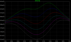
I tend to look at the small signal output impedance with various DC (op.point) output currents and voltages to check 4-quadrants-OS linearity, in this case I find that Zout bounces around between 250mR and 300mR, also some change with freq (see attachment, note I didn't scale in Ohms, just forgot to put the "V(OUT)/1A)" there).
Color sequence is LTspice standard:
green, blue, red, cyan, magenta, grey, d.green, d.blue, brown, violet, d.brown.
Each color is a 0.5A step (0...5A range, 11 steps), with outputs voltages 0V/10V/30V in top-down order. So its actually only some op points in the first quadrant, but it shows enough, I think.
More or less what I expected...
- Klaus
Attachments
FWIW, with Rbias= ~2.9k I was able to sim a pretty constant Zout up to ~1A Iout, and above that it decreases monotonically with current... something I tend to like, a stable/flat transconductance for lower load levels and a monotonic increase for higher levels, because I'm more concerned about distortion in the low load range. With those 3.4k Zout is quite non-monotonic in that (to me) important range --> more and higher order distortion.
- Klaus
- Klaus
I've attached a plot of the simulated nonlinear DC output resistance d(V(out))/d(I(out)) with Iout going from -1A to +1A. For +1A, the amp is sourcing current, thus the minus sign in the expression for the derivative. Rbias is stepped from 2.9k to 3.4k in 100 Ohm steps. The topmost curve is 2.9k and the bottom is 3.4k. You can see the overbias condition at 3.4k (small-signal Rout much less than large-signal Rout).
Attachments
ostripper said:That is seriously cool...you can include a whole .txt in the
comment.
Hi OS - Just to clarify, there are comments and "SPICE directives". Comments are shown in blue text in the standard LTspice color scheme, while SPICE directives are shown in black. Technically speaking, the ".include somefile.txt" is a SPICE directive. You can change a SPICE directive to a comment (or vice versa) by right-clicking on it and choosing the appropriate option of the "how to netlist this text" radio buttons. It's instructive to see how this works by doing a "View, SPICE netlist" after a simulation of a very minimal circuit. Once you see the connection between the directives and comments on the schematic and what goes into the netlist, you can combine that information with the documentation for the "dot commands" and do some interesting things. Conceptually, you can think of the simulator proper as a kind of command-line utility that gets passed the netlist's file name as a command-line argument, processes the netlist, and sends information back to the UI in the form of a somefile.raw file. It may not actually be implemented this way though.
Edit - what sort of freaky magic is this.. it ran 25 different
simulations with stepped biasing , bottomed out at .02 at
3400R , so now we know what it can do in isolation..
That is the SPICE directive:
.step param Rbias 1.5k 4k 100
at work. This says basically, "Define a parameter named Rbias that goes from 1.5k to 4k in steps of 100, and perform a simulation for each value of Rbias". Combined with the {Rbias} notation for setting the value of the component makes it work. You can try commenting this directive out as described above, then "un-commenting" the ".param Rbias 3400" to switch between a single simulation and multiple ones.
Sorry for the OT.
Andy_c
Good info for newbies to sim s/w like myself - is there a thread on this forum for explaining how to use sim s/w - I don't want to pollute this thread but I'd like to sim this circuit?
Good info for newbies to sim s/w like myself - is there a thread on this forum for explaining how to use sim s/w - I don't want to pollute this thread but I'd like to sim this circuit?
See the sticky "SPICE simulation" thread. That thread was actually created by the mods, who combined various groups of posts together from other threads. It's evolved into a kind of support thread despite the (IMO useless) "flame war" nature of the first three or four pages.
Thanks for that, Andy. A perfect complement to the graph I've shown.andy_c said:I've attached a plot of the simulated nonlinear DC output resistance d(V(out))/d(I(out)) with Iout going from -1A to +1A.
-------:-------
@Steve: Personally, I have no reason to doubt the numbers you claim for this design, simming is NOT reality especially when we operate devices "on the edge" (low Vce in this case) where the models quite probably will have serious flaws. Just wanted to make that point clear...
- Klaus
jwb said:Nulling the distortion into a perfect 8R dummy load seems sort of pointless.
I'm open to suggestions. How would you do it?
Thanks andy_c, but at 3.4K the output idles at ~250mA? Your files ran with no changes needed. At low currents the crossover returns.
There are a lot of stored charges flying around and I'm still looking for what I call an FEA (fortuitious empirical artifact) that actually causes the nulling behavior.
There are a lot of stored charges flying around and I'm still looking for what I call an FEA (fortuitious empirical artifact) that actually causes the nulling behavior.
Yes, it's overbiased as shown in the graph in this post.
Interestingly, I tried this with just the output devices with constant voltage drive. In that case, the bias current that gave minimum distortion was 100 mA - about the optimum for Re=0.22 Ohms.
Interestingly, I tried this with just the output devices with constant voltage drive. In that case, the bias current that gave minimum distortion was 100 mA - about the optimum for Re=0.22 Ohms.
andy_c said:Yes, it's overbiased as shown in the graph in this post.
Interestingly, I tried this with just the output devices with constant voltage drive. In that case, the bias current that gave minimum distortion was 100 mA - about the optimum for Re=0.22 Ohms.
Yes, what is hard to picture totally is the behavior of the nearly saturated transistors. In a normal triple there is a string of Vbe's that define the input to output transfer function. Here you actually can inject some voltage via the Vcb of those transistors. That is where I was looking for some interesting action.
- Status
- Not open for further replies.
- Home
- Amplifiers
- Solid State
- Krill - The little amp that might...